Sealing structure

A technology of sealing structure and outer peripheral surface, which is applied in the direction of engine sealing, engine sealing device, machine/engine, etc., can solve the problem of sealing ring 120 expansion and deformation, and achieve excellent sealing effect

Active Publication Date: 2015-04-22
NOK CORP
View PDF5 Cites 4 Cited by
  • Summary
  • Abstract
  • Description
  • Claims
  • Application Information

AI Technical Summary

Problems solved by technology

[0011] However, according to the above-mentioned conventional sealing structure, the following problem has been pointed out: in the work of mounting the seal ring 120 on the mounting part outer peripheral surface 112 of the injector 110, the outer peripheral surface of the front end part whose diameter is larger than that of the mounting part outer peripheral surface 112 In the process of 114, the sealing ring 120 is subjected to diameter expansion deformation

Method used


Image

  • Sealing structure
  • Sealing structure
  • Sealing structure

Examples


Embodiment approach 1

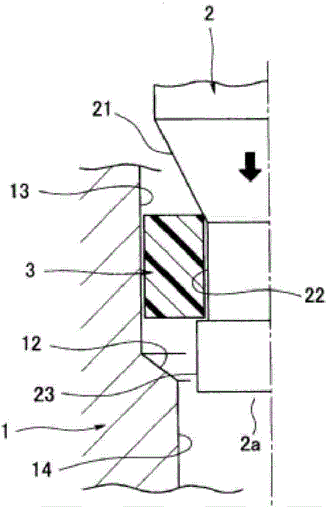
[0066] In addition, after installing the seal ring 3 on the image 3 In the state, first, the seal ring 3 is inserted in advance from the front end side of the nozzle 2a of the injector 2 to the outer peripheral surface 22 of the mounting part. In addition, this is also the same as the first embodiment described above. If the outer diameter ΦA of the mounting portion outer peripheral surface 22 and the outer diameter ΦB of the front end outer peripheral surface 23 have a relationship of 100%<ΦB / ΦA<110%, then The diameter of the seal ring 3 is slightly enlarged when it passes over the front end outer peripheral surface 23 , so residual deformation of the seal ring 3 can be effectively prevented.

[0067] Next, if Figure 4 As shown in (a), the injector 2 on which the seal ring 3 is inserted is inserted into the injector mounting hole 11 of the cylinder head 1 . Thus, during this insertion, first, if Figure 4 As shown in (b), the end surface outer diameter portion 3 a of the...


PUM


Abstract

The purpose of the present invention is to provide a sealing structure for which the man-hours for seal ring installation are not high and with which excellent sealing properties can be obtained. To achieve said purpose, a seal ring (3) is interposed between an outer member (1) and an inner member (2) fitted by being inserted in the outer member (1). On the outer circumferential surface of the inner member (2), a tapered outer circumferential surface (21), the diameter of which decreases in the direction of insertion of the inner member (2), and an installation section outer circumferential surface (22) that extends from the small diameter end in the insertion direction are formed. On the inner circumferential surface of the outer member (1), a stepped surface (12) located further in the insertion direction than the tapered outer circumferential surface (21) and facing the direction opposite to insertion and an installation section inner circumferential surface (13) extending from the outer diameter edge of the stepped surface (12) in the direction opposite to insertion are formed. The seal ring (3) is disposed in a compressed state between the tapered outer circumferential surface (21) and installation section outer circumferential surface (22) and the stepped surface (12) and installation section inner circumferential surface (13).

Description

technical field [0001] The present invention relates to a sealing structure for sealing the gap between an outer peripheral member and an inner peripheral member inserted into the outer peripheral member, and particularly relates to a seal suitable for high-pressure gas, such as an internal combustion engine. It is a sealing structure that seals the gap between the mounting hole of the cylinder head and the front end of the injector, combustion pressure sensor, cylinder pressure sensor, etc. that are inserted into the mounting hole. Background technique [0002] The direct-injection internal combustion engine directly injects fuel into the cylinder through the injector. Since the injector is installed in the injector mounting hole opened in the cylinder head in an inserted state, in order to prevent the combustion gas from flowing through the injector mounting hole The gap between the inner peripheral surface and the outer peripheral surface of the injector generates a leak,...

Claims


Application Information

Patent Timeline
Patent Type & Authority Applications(China)
IPC IPC(8): F16J15/10F02M61/16
CPCF16J15/106F02M61/14F02M2200/858F16J15/062F02F11/002F02F1/242F16L21/035
Inventor 但野光夫马启仁安田宏通
Owner NOK CORP
Why Eureka
Try Eureka