
PTC heating core heat pipe rolling device

A technology of heat pipe and heating core, which is applied in the field of heat pipe rolling device of PTC heating core, can solve problems such as damage to heat pipe, failure of rolling, and defects of heat pipe, so as to achieve convenient use and maintenance, avoid transitional deformation, and facilitate The effect of production

Active Publication Date: 2016-04-27
嘉善县魏塘资产管理有限公司
View PDF13 Cites 0 Cited by
  • Summary
  • Abstract
  • Description
  • Claims
  • Application Information

AI Technical Summary

Problems solved by technology

But this patent application scheme still has the following shortcomings: one, due to the need to simultaneously roll the two edge positions of the upper and lower surfaces of the heat pipe, that is, there are four rolling positions, so the upper rolling roll and the lower rolling roll Complex structure, difficult processing
In particular, once there is even a slight deviation in the position of the upper and lower relief passages of the heat dissipation strips on a group of upper calendering rollers and a group of lower calendering rollers, it will cause the heat pipe to be defective or even scrapped; While rolling the upper and lower surfaces of the heat pipe, the front and rear sides of the heat pipe will tend to bulge away from the heat conduction lumen, so that the front and rear sides of the PTC heating core accommodated in the heat conduction lumen are difficult to contact with the heat conduction lumen. The good contact between the front and rear walls of the heat pipe affects the heat transfer effect of the front and rear walls of the heat pipe; thirdly, due to the unreasonable structure of the introduction mechanism (the patent is called the heating core heat pipe introduction mechanism), the introduction resistance is relatively large , and even damage the heat pipe due to the intense friction between the front and rear walls of the heat pipe and the groove walls of the guide grooves of the two introduction seats; Fourth, because the power transmission mechanism needs to use a plurality of bevel gear pairs, the structure is complex and difficult to manufacture Fifth, since the upper rolling roller cannot be adjusted up and down relative to the lower rolling roller, it is picky about the specifications of the heat transfer tube. For example, when the specification of the heat transfer tube changes, it cannot be rolled.

Method used


Image

  • PTC heating core heat pipe rolling device
  • PTC heating core heat pipe rolling device

Examples


Embodiment Construction

[0022] In order to enable the examiners of the patent office, especially the public, to understand the technical essence and beneficial effects of the present invention more clearly, the applicant will describe in detail the following in the form of examples, but none of the descriptions to the examples is an explanation of the solutions of the present invention. Any equivalent transformation made according to the concept of the present invention which is merely formal but not substantive shall be regarded as the scope of the technical solution of the present invention.

[0023] In the following descriptions, all concepts involving up, down, left, right, front and rear directionality (or orientation) are for the position state of the picture being described, and the purpose is to facilitate the public Therefore, it cannot be understood as a special limitation on the technical solution provided by the present invention.

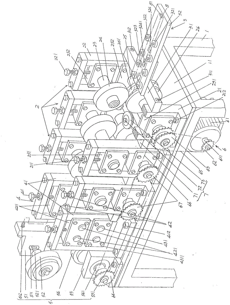
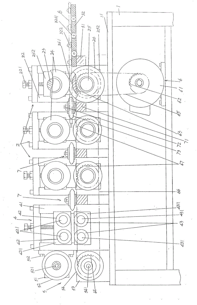
[0024] See figure 1 and figure 2 , provides: a frame ...


PUM


Abstract

The invention discloses a roll compacting device of a PTC (positive temperature coefficient) heating core heat conduction pipe and belongs to the field of a special device for manufacturing a PTC heater. The roll compacting device comprises a rack on which a working table is arranged, one group of heat conduction pipe holding mechanisms, a heat conduction pipe leading-in mechanism, a heat conduction pipe transition leading-out mechanism, a heat conduction pipe leading-out mechanism, a power transmission mechanism, and one group of heat conduction pipe roll compacting mechanisms, wherein each heat conduction pipe holding mechanism respectively includes front and rear axle bases, an upper roller disc shaft, an upper roller disc, a lower roller disc shaft and a lower roller disc; the heat conduction pipe leading-in mechanism comprises a guide plate fixing cross rod and a guide plate, and one group of front and rear guide wheels of the guide plate is arranged on the guide plate; the heat conduction pipe leading-out mechanism comprises an upper leading-out axle base, an upper leading-out wheel, a lower leading-out axle base and a lower leading-out wheel; the power transmission mechanism comprises a motor, a main transmission wheel, a lower roller disc shaft transmission wheel, a lower leading-out axle transmission wheel, a main transmission belt and a transition transmission belt; one group of heat conduction pipe roll compacting mechanisms is distributed on the left side of each heat conduction pipe holding mechanism and corresponding to the left side of the passageway between upper and lower roller discs.

Description

technical field [0001] The invention belongs to the technical field of special devices for the manufacture of PTC heaters, and in particular relates to a PTC heat-conducting core heat-conducting tube rolling device, which is used to simultaneously apply external force to the corresponding positions of the front and rear tube walls in the length direction of the heat-conducting tube to form the tube wall The concave cavity, which is V-shaped, U-shaped or W-shaped in cross-section and recessed into the lumen, enables the heating core disposed in the lumen of the heat pipe to be reliably positioned in the lumen. Background technique [0002] The PTC mentioned above refers to a positive temperature coefficient thermistor. The PTC heater mentioned above is widely seen in the published Chinese patent documents. For example, the authorized announcement number CN2512191Y (improved PTC heater and special-purpose fixed bracket), CN2181789Y (fully enclosed surface uncharged PTC heater)...

Claims


Application Information

Patent Timeline
Patent Type & Authority Patents(China)
IPC IPC(8): B21D17/04B21D43/08
Inventor 黄明峰
Owner 嘉善县魏塘资产管理有限公司
Learn More