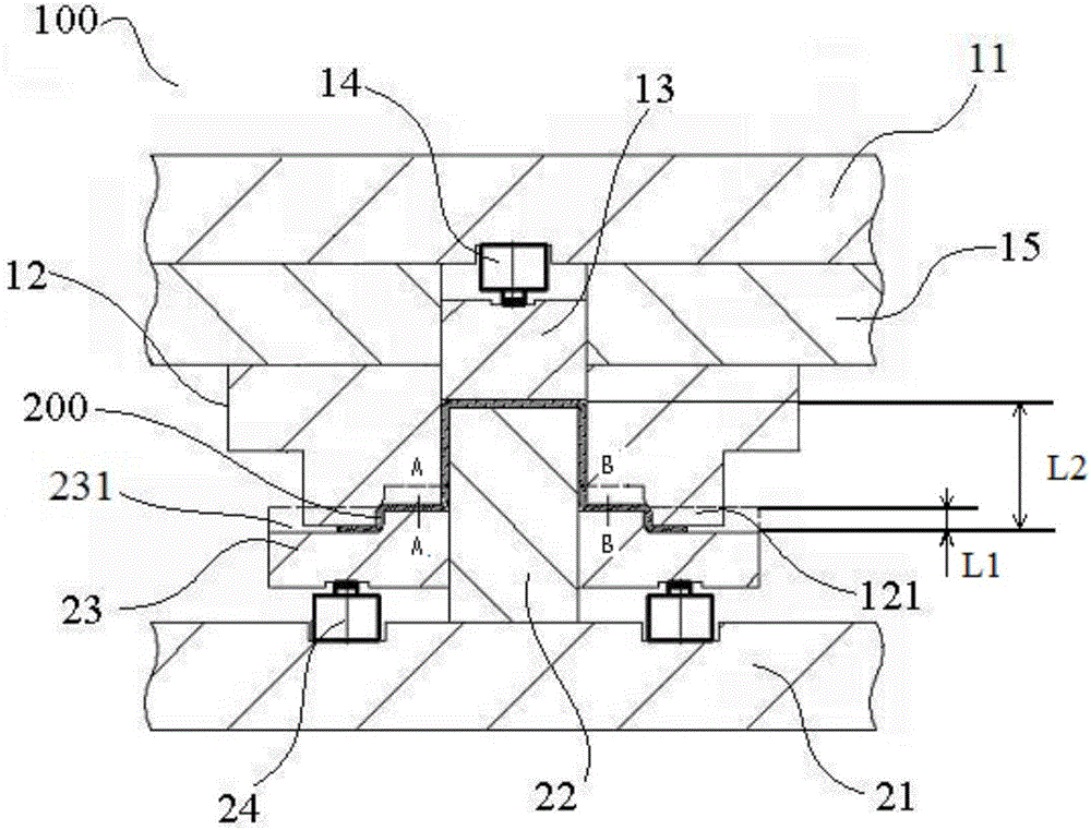
Die structure

A mold and concave mold technology, applied in the field of mold structure, can solve the problems of curling and springback of the side wall of the workpiece, inconsistent deformation, uneven stress distribution on the inner and outer surfaces of the workpiece, etc., and achieve the effect of uniform stress distribution

Inactive Publication Date: 2015-04-29
BEIQI FOTON MOTOR CO LTD
View PDF4 Cites 4 Cited by
  • Summary
  • Abstract
  • Description
  • Claims
  • Application Information

AI Technical Summary

Problems solved by technology

[0002] When the traditional mold structure is used to stamp high-strength steel sheets, due to the rounded corners of the punch and die, the stress distribution on the inner and outer surfaces of the workpiece is uneven, and the deformation is inconsistent. Recovery, the stress on the inner and outer surfaces of the workpiece will change, so that the side wall of the workpiece is prone to curling and springback

Method used


Image

  • Die structure

Examples


Embodiment Construction

[0024] Embodiments of the present invention are described in detail below, examples of which are shown in the drawings, wherein the same or similar reference numerals designate the same or similar elements or elements having the same or similar functions throughout. The embodiments described below by referring to the figures are exemplary and are intended to explain the present invention and should not be construed as limiting the present invention.

[0025] In the description of the present invention, it should be understood that the orientation or positional relationship indicated by the terms "upper", "lower", "vertical", "inner", "outer", "height" etc. The orientation or positional relationship is only for the convenience of describing the present invention and simplifying the description, but does not indicate or imply that the device or element referred to must have a specific orientation, be constructed and operated in a specific orientation, and therefore cannot be cons...


PUM


Abstract

The invention discloses a die structure comprising a female die component and a male die component. The male die component is arranged under the female die component and comprises a die holder, a male die arranged on the die holder and a pressing plate. The pressing plate penetrates the male die to be vertically movably arranged on the die holder. The distance of the vertical movement of the pressing plate is less than stretching depth of a workpiece. As the female component moves downwards to be matched with the pressing plate, the pressing plate and the female component synchronously move downwards, and preset deformation occurs to the edge of the workpiece. According to the arrangement, as the distance of the vertical movement of the pressing plate is less that vertical height of the sidewall of the workpiece stamped, the workpiece is applied with low acting force by a fillet of the female die component, the enough deformation occurs to the sidewall of the workpiece, and accordingly stress is uniformly distributed on the inner and the outer surfaces of the workpiece without curling and springs back.

Description

technical field [0001] The invention relates to the field of stamping equipment, in particular to a mold structure. Background technique [0002] When the traditional mold structure is used to stamp high-strength steel sheets, due to the rounded corners of the punch and die, the stress distribution on the inner and outer surfaces of the workpiece is uneven, and the deformation is inconsistent. Recovery, the stress on the inner and outer surfaces of the workpiece will change, so that the side wall of the workpiece is prone to curling and springback. Contents of the invention [0003] The present invention aims to solve at least one of the technical problems existing in the prior art. Therefore, an object of the present invention is to provide a mold structure, which can effectively control the curling and springback of the side wall of the high-strength steel plate during the stamping forming process, and improve the forming accuracy and quality of the stamping parts of th...

Claims


Application Information

Patent Timeline
Patent Type & Authority Applications(China)
IPC IPC(8): B21D37/10
CPCB21D37/10
Inventor 袁卉卢世锋周广路么学刚郝建东
Owner BEIQI FOTON MOTOR CO LTD
Why Eureka
Try Eureka