
Heat radiation structure of milling cutter

A heat dissipation structure and milling cutter technology, which is applied to milling cutters, milling machine equipment, manufacturing tools, etc., can solve problems such as shortening the life of milling cutters

Inactive Publication Date: 2015-04-29
常州市海伦工具有限公司
View PDF0 Cites 0 Cited by
  • Summary
  • Abstract
  • Description
  • Claims
  • Application Information

AI Technical Summary

Problems solved by technology

Existing milling cutters are not equipped with a special cooling structure, and when the heat is severe, it directly leads to shortening of the life of the milling cutter

Method used


Image

  • Heat radiation structure of milling cutter

Examples


Embodiment Construction

[0010] The present invention will be further described below in conjunction with the accompanying drawings.

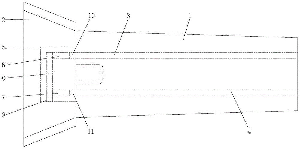
[0011] refer to figure 1 , the heat dissipation structure of the milling cutter of the present invention includes a handle 1 and a cutter head 2 fixedly connected with the handle, the handle is provided with a coolant input hole 3 and a coolant output hole 4, the middle of the cutter head A mounting hole is provided, and a threaded hole is provided on the axial end surface of the knife handle, and the knife handle 1 is fixedly connected with the cutter head 2 through a screw 5 . The axial end surface of the screw is provided with a first axial hole 6 and a second axial hole 7, and the circumferential surface of the screw is provided with a radial hole 8, and the two ends of the radial hole 8 are connected to the first axial hole respectively. The hole 6 communicates with the second axial hole 7, and the opening of the radial hole 8 is provided with a plug 9. After the...


PUM


Abstract

The invention relates to a heat radiation structure of a milling cutter. The heat radiation structure of the milling cutter comprises a handle and a cutter head fixedly connected with the handle, wherein a cooling liquid input hole and a cooling liquid output hole are formed in the handle; a mounting hole is formed in the middle of the cutter head; a threaded hole is formed in the axial end surface of the handle; the handle is fixedly connected with the cutter head through a screw; a first axial hole and a second axial hole are formed in the axial end surface of the screw; a radial hole is formed in the circumferential surface of the screw; two ends of the radial hole are communicated with the first axial hole and the second axial hole respectively; a plug is arranged at the orifice of the radial hole; and after the handle and the cutter head are fixed through the screw, the cooling liquid input hole in the handle is communicated with the fist axial hole, and the cooling liquid output hole is communicated with the second axial hole in the screw. The heat of the milling cutter in a working process can be radiated effectively, and the service life of the milling cutter is guaranteed.

Description

technical field [0001] The invention relates to a heat dissipation structure of a milling cutter. Background technique [0002] The existing milling cutter is made up of a milling cutter head and a milling cutter shaft, the milling cutter head is fixedly arranged on one end of the milling cutter shaft, and the cutting edge of the milling cutter head is arranged on the circumference of the milling cutter head. Because the milling cutter rotates at a high speed to cut the workpiece during the working process, the heat is more serious during the cutting process, and the performance of the milling cutter head plummets after the heat is generated. Existing milling cutters are not provided with a dedicated cooling structure, and when the heat is severe, the life of the milling cutter is shortened directly. Contents of the invention [0003] Aiming at the deficiencies of the prior art, the present invention provides a heat dissipation structure of the milling cutter, which can e...

Claims


Application Information

Patent Timeline
IPC IPC(8): B23C5/28
CPCB23C5/28
Inventor 曹大龙
Owner 常州市海伦工具有限公司
Learn More