Injection upper mold with cooling for injection molding of fan blades

A fan blade and injection molding technology, which is applied in the field of injection molding upper mold, can solve the problems of reducing product qualification rate, etc., and achieve the effects of convenient mold design, improved smooth speed, and accelerated cooling and shaping

Active Publication Date: 2015-04-29
ANHUI ANYUAN PLASTIC
View PDF5 Cites 1 Cited by
  • Summary
  • Abstract
  • Description
  • Claims
  • Application Information

AI Technical Summary

Problems solved by technology

[0002] At present, in the production of fan blades such as CPUs, the injection molding method is commonly used, and the production efficiency is fast. If the molds usually used are in mass production, their structures are more complicated. When the structure is more complicated, it will bring many problems in the design, such as : 1. The uniformity of heating; 2. The distribution of vent holes; 3. The distribution of feed ports. If the above problems are not handled properly, the qualified rate of the product will be reduced.

Method used


Image

  • Injection upper mold with cooling for injection molding of fan blades
  • Injection upper mold with cooling for injection molding of fan blades
  • Injection upper mold with cooling for injection molding of fan blades

Examples


Embodiment 1

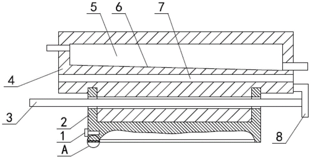
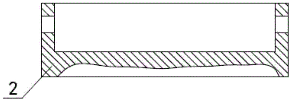
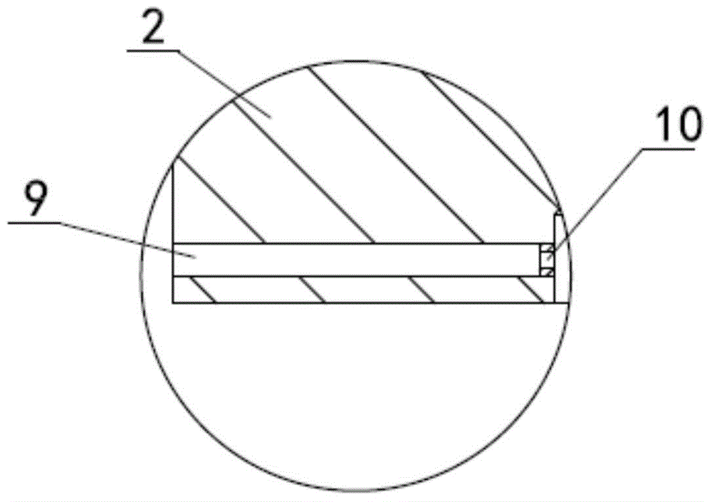
[0018] like figure 1 , figure 2 , image 3 As shown, the injection molding upper mold with cooling for fan blade injection includes an upper mold body 2, an injection channel 9 is horizontally provided at the lower left part of the upper mold body 2, and a piece for the upper mold body 2 is arranged on the upper part of the upper mold body 2. The heated aluminum block 4 is provided with a groove downwards on the upper surface of the upper mold body 2, and the lower surface of the heated aluminum block 4 extends downwards with a protrusion matching the groove, and a heating aluminum block 4 is provided with a The heating chamber 5 for steam heating, the heating aluminum block 4 on the left side of the heating chamber 5 is provided with a steam inlet, the heating aluminum block 4 on the right side of the heating chamber 5 is provided with a steam outlet, and the bottom surface of the heating chamber 5 is a left The inclined surface 6 is high and right low, and a cooling water...

Embodiment 2

[0022] This embodiment is changed on the basis of Embodiment 1, the left exposed end of the connecting rod 3 is changed to 400 mm; the diameter of the connecting rod 3 is changed to 40 mm; the distance between the electric heating rod 1 and the injection channel 9 The distance becomes 15mm. Others are the same as embodiment one.

Embodiment 3

[0024] This embodiment is changed on the basis of Embodiment 1, the left exposed end of the connecting rod 3 is changed to 500 mm; the diameter of the connecting rod 3 is changed to 50 mm; the distance between the electric heating rod 1 and the injection channel 9 The distance becomes 20mm. Others are the same as embodiment one.


PUM

PropertyMeasurementUnit
diameteraaaaaaaaaa

Abstract

The invention relates to an injection upper mold with cooling for injection molding of fan blades and belongs to the technical field of injection molds. The injection upper mold with cooling comprises an upper mold body, wherein an injection channel is horizontally arranged at the bottom left part of the upper mold body, a heating aluminum block for heating the upper mold body is arranged at the upper part of the upper mold body, a groove is downwards formed in the upper surface of the upper mold body, a convex block matched with the groove downwards extends from the lower surface of the heating aluminum block, a heating cavity for steam heating is arranged in the heating aluminum block, the bottom surface of the heating cavity is an inclined plane which is high at the left and low at the right, a cooling water cavity is transversely formed in the heating aluminum block below the heating cavity, a boss with an annular structure is arranged on the inner side wall of the injection channel, and an electric heating bar is arranged on the upper mold body above the injection channel by penetration. The injection upper mold with cooling, provided by the invention, has the advantages of simple structure, uniform heating of the upper mold body, high heating speed, high production efficiency and convenience in mounting, and can ensure the product qualification rate.

Description

technical field [0001] The invention relates to an injection upper mold with cooling for injection molding of fan blades, belonging to the technical field of injection molds. Background technique [0002] At present, in the production of fan blades such as CPUs, the injection molding method is commonly used, and the production efficiency is fast. If the molds usually used are in mass production, their structures are more complicated. When the structure is more complicated, it will bring many problems in the design, such as : 1. The uniformity of heating; 2. The distribution of vent holes; 3. The distribution of feed ports. If the above problems are not handled properly, the qualified rate of the product will be reduced. Contents of the invention [0003] In view of the above problems, the present invention provides a cooling upper mold for injection molding of fan blades, which has a simple structure, convenient operation, uniform heating, avoids the influence of uneven he...

Claims


Application Information

Patent Timeline
Patent Type & Authority Applications(China)
IPC IPC(8): B29C45/26B29C45/73B29L31/08
CPCB29C45/26B29C45/345B29C45/73B29L2031/08
Inventor 刘绍明
Owner ANHUI ANYUAN PLASTIC
Why Eureka
Try Eureka