Flapping wing capable of automatically folding and unfolding for flapping wing type micro aerial vehicle

A micro-aircraft, automatic technology, applied in aircraft, motor vehicles, transportation and packaging, etc., can solve the problems of flapping-wing micro-aircraft with few foldable flapping wings, high requirements for carrying conditions, and less research on flapping wing structures , to achieve the effect of improving versatility and interchangeability, maintaining flight performance and improving service life

Inactive Publication Date: 2015-04-29
JILIN UNIV
View PDF5 Cites 19 Cited by
  • Summary
  • Abstract
  • Description
  • Claims
  • Application Information

AI Technical Summary

Problems solved by technology

Therefore, the area of ​​these flapping wings is often relatively large, the strength is low, easy to damage, the requirements for carrying conditions are high, and it is not convenient to carry
Currently, research on flapping wings for bionic flapping-win

Method used


Image

  • Flapping wing capable of automatically folding and unfolding for flapping wing type micro aerial vehicle
  • Flapping wing capable of automatically folding and unfolding for flapping wing type micro aerial vehicle
  • Flapping wing capable of automatically folding and unfolding for flapping wing type micro aerial vehicle

Examples


Embodiment Construction

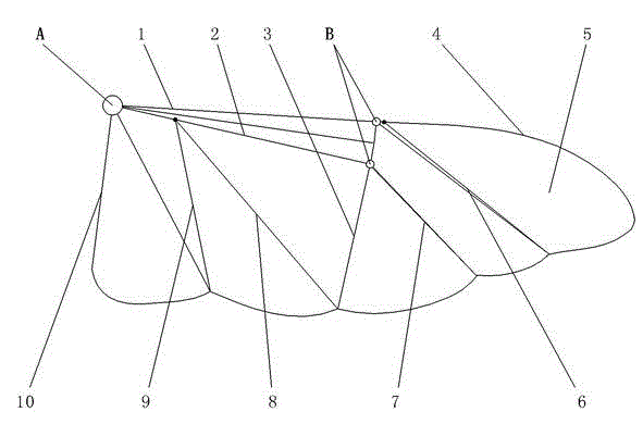
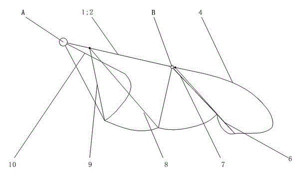
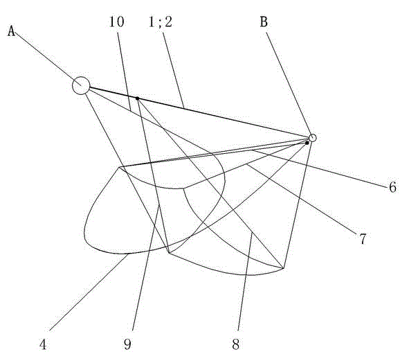
[0030] see figure 1 , figure 2 with image 3 As shown, the present invention is composed of a power unit A, a first hydraulic pipe 1, a second hydraulic pipe 2, several creases 3, a first support rod 4, a second support rod 6, a third support rod 7, and a fourth support rod. Composed of rod 8, fifth support rod 9, sixth support rod 10, wing membrane 5 and two folding devices B; first hydraulic pipe 1, second hydraulic pipe 2 and sixth support rod 10 are radially distributed in power unit A Around, the ends of the first support rod 4, the second support rod 6, the third support rod 7, the fourth support rod 8, the fifth support rod 9 and the sixth support rod 10 are suspended;

[0031] see Figure 4 , Figure 5 with Image 6 As shown, the power device A includes two liquid chambers 11, a two-way micro-flow pump 12, several inelastic hoses 13, wing handles 14, two elastic members 15, hollow link members 16, common hinges 17, Two micro-sensors 23, a microcontroller 25 and ...


PUM


Abstract

The invention discloses a flapping wing capable of automatically folding and unfolding for a flapping wing type micro aerial vehicle. The flapping wing consists of a power device, two hydraulic pipes, a plurality of creases, a plurality of supporting rods, a wing membrane and two folding devices, and the folding and unfolding of the flapping wing are realized by adopting a hydraulic principle. According to the flapping wing, the two hydraulic pipes and the plurality of supporting rods form wing veins of a bionic flapping wing, and the wing membrane is adhered to the bionic wing veins to form a wing surface. The flapping wing pumps liquid into different liquid chambers by virtue of a micro flow pump to generate a pressure so as to drive the flapping wing to fold up or unfold. The flapping wing disclosed by the invention has the beneficial effects of reducing the transverse size of flapping wing type micro aerial vehicle when the flapping wing type micro aerial vehicle does not fly, reducing the spaces required for carrying, transportation and storage, reducing transportation requirements, conveniently protecting the flapping wing of the aerial vehicle from being damaged, favorably replacing a damaged flapping wing to improve the service life of the micro aerial vehicle.

Description

technical field [0001] The invention relates to a foldable and unfoldable flapping wing of a flapping-wing aircraft, in particular to an automatically foldable and unfoldable flapping wing of a bionic flapping-wing micro-aircraft. Background technique [0002] Since American scientists proposed the concept of micro-aircraft in 1992, in view of its huge application value in military and civilian fields, many researchers at home and abroad have launched research on related fields of micro-aircraft. After more than 20 years of development, MAVs have formed three main types: fixed-wing, rotary-wing and flapping-wing. Because flapping-wing MAVs can still generate sufficient lift and thrust under smaller scales and weights, they have become one of the research hotspots in the field of MAVs. [0003] In order to make the flapping-wing MAV have good aerodynamic performance under smaller size and weight, most of its flapping wings adopt membrane structure. In order to provide suffi...

Claims


Application Information

Patent Timeline
IPC IPC(8): B64C33/02
Inventor 张志君吴永锋刘丽杰邴政孙霁宇
Owner JILIN UNIV
Why Eureka
Try Eureka