Construction structure of cylindrical die

A column and formwork technology, which is applied in the direction of house structure support, house structure support, formwork/formwork/work frame, etc., can solve the problems of circular steel formwork not reaching the number of turnovers, large initial investment, and long customization time. , to achieve the effect of improving pouring quality and construction safety, improving construction technology and strengthening effect.

Inactive Publication Date: 2015-04-29
ZHONGTIAN CONSTR GROUP
View PDF6 Cites 9 Cited by
  • Summary
  • Abstract
  • Description
  • Claims
  • Application Information

AI Technical Summary

Problems solved by technology

Among them, the steel mold method is a better solution, but the initial investment is relatively large, and the customization time is relatively long. Moreover, due to the diversity of architectural designs, the use of circular steel molds cannot achieve the ideal turnover times, so the construction is not economical. , the use of general projects is relatively small; when the amount of circular column engineering is relatively small, it is also a method to use sheet wood formwork in bulk, but the quality of the problem cannot be guaranteed, and the appearance is not good. If it is made of clear water formwork, it will not work at all; there is another The method is that the corrugated pipe acts as a formwork. Although the surface appearance after concrete pouring can meet the requirements, the corrugated pipe cannot be reused, and the joints at the beam-column joints cannot achieve the expected effect. It is not as convenient to use as the previous two methods; recently we use a The new cylindrical construction method uses the finished round formwork for construction and uses clamps for reinforcement, which can well make up for the defects of the previous three methods and better meet the current construction requirements

Method used


Image

  • Construction structure of cylindrical die
  • Construction structure of cylindrical die
  • Construction structure of cylindrical die

Examples


Embodiment Construction

[0012] The present invention will be further described now in conjunction with accompanying drawing

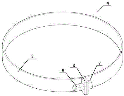
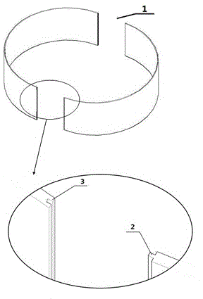
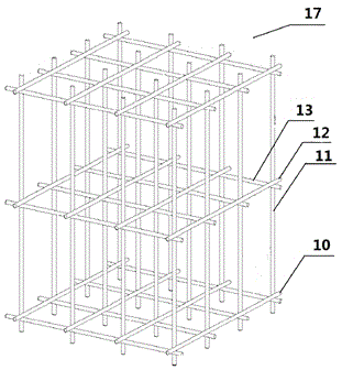
[0013] A construction structure of a cylindrical mold, the cylindrical mold is a formwork for pouring cylindrical concrete, the formwork consists of two formed semicircular formwork 1 with convex grooves 2 and grooves 3 on both sides of the formwork, Two semi-circular formworks bite into each other to form a hollow cylindrical formwork; the feature is: on the outside of the hollow cylindrical formwork, the formwork is surrounded by steel bar hoops at equal intervals and fastened, and the hollow cylindrical formwork is vertically inserted in double rows In the middle of the scaffolding; the templates are stacked to the required height, and the joints are connected by steel column hoops; at the 2 / 3 elevation of the cylindrical formwork, a throwing support structure 14 is set to ensure the verticality and stability of the column.

[0014] Described steel column hoop is that steel...


PUM


Abstract

The invention discloses a construction structure of a cylindrical die, relates to the technical field of building construction and relates to design technology of an auxiliary tool for building construction, in particular to the construction structure of the cylindrical die. The construction structure is characterized in that the outer side of a hollow cylindrical template is fastened by muffling the template by steel strip post hoops at equal intervals; the hollow cylindrical template is vertically inserted into the middle of a dual-row scaffold; templates are overlapped to required height, and seams are connected by the steel strip post hoops; at the two thirds elevation of the cylindrical die, a throwing support structure used for guaranteeing the perpendicularity and the stability of a post is arranged. The construction structure has the positive effects that a post hoop material is simple, construction is convenient to perform, and a cylinder reinforcing effect is good; the safety of workers during construction can be guaranteed by the dual-row scaffold which encloses a cylinder; throwing support steel pipes and short steel pipes form a whole, so that the stability of the cylinder and the perpendicularity of concrete can be effectively controlled; the problem of poor reinforcing quality of a cylinder in a construction field is solved by the structure, and the construction process is improved.

Description

technical field [0001] The utility model belongs to the technical field of building construction, and relates to the design technology of auxiliary tools for building construction, specifically the construction structure of concrete cylindrical formwork. Background technique [0002] According to the design drawings, circular columns are often encountered in building construction. The construction methods of circular columns are currently more common: steel mold method, sheet wood mold bulk method, and corrugated pipe method. Among them, the steel mold method is a better solution, but the initial investment is relatively large, and the customization time is relatively long. Moreover, due to the diversity of architectural designs, the use of circular steel molds cannot achieve the ideal turnover times, so the construction is not economical. , the use of general projects is relatively small; when the amount of circular column engineering is relatively small, it is also a metho...

Claims


Application Information

Patent Timeline
Patent Type & Authority Applications(China)
IPC IPC(8): E04G13/02E04G1/36E04G1/04
Inventor 邓凌云周孟东叶文启陈忠徐立胜
Owner ZHONGTIAN CONSTR GROUP
Why Eureka
Try Eureka