
Continuous shocking tool

A technology of tools and jackets, which is applied in the direction of wellbore/well components, earthwork drilling and production, etc., can solve the problems of reduced jarring efficiency, poor jarring effect, and damage to operating strings, so as to improve reliability and beautiful appearance degree, the effect of improving structural stability

Active Publication Date: 2015-04-29
JEREH ENERGY SERVICES
View PDF5 Cites 117 Cited by
  • Summary
  • Abstract
  • Description
  • Claims
  • Application Information

AI Technical Summary

Problems solved by technology

At present, after one shock with conventional jars, it is necessary to lift up or lower the pipe string to reset it before performing the second shock. While the shock effect is not good, the operating pipe string needs to be lifted up and down repeatedly, not only The shock efficiency is reduced, and it is easy to cause damage to the working string due to fatigue work

Method used


Image

  • Continuous shocking tool
  • Continuous shocking tool
  • Continuous shocking tool

Examples


Embodiment Construction

[0022] The principles and features of the present invention are described below in conjunction with the accompanying drawings, and the examples given are only used to explain the present invention, and are not intended to limit the scope of the present invention.

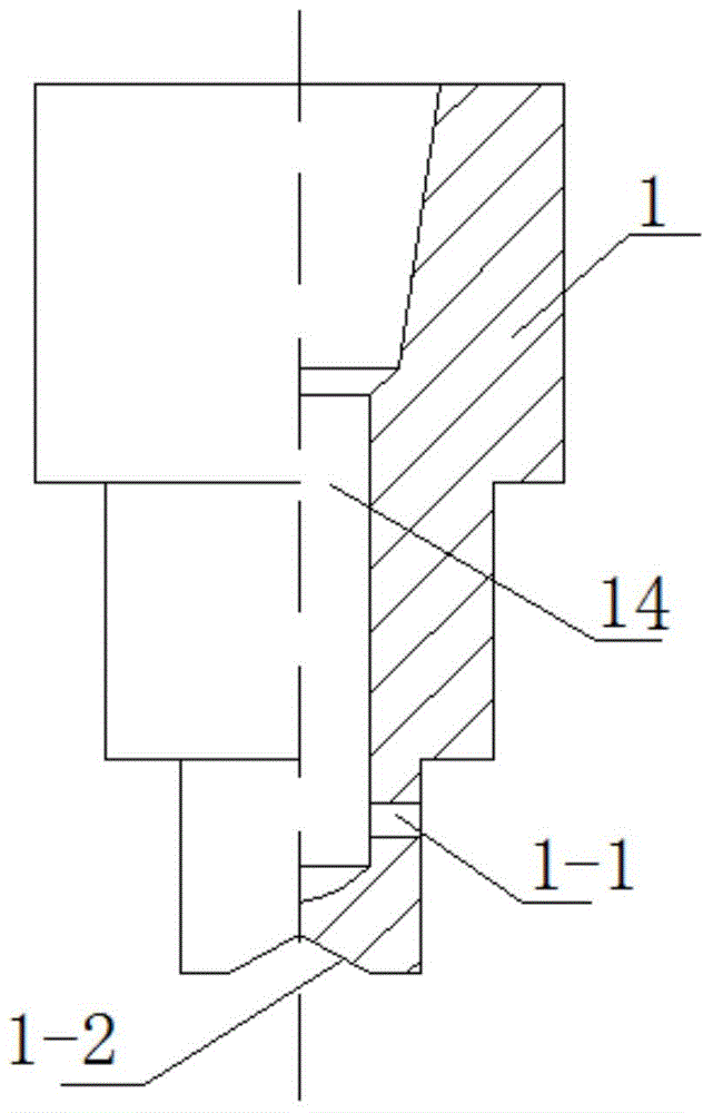
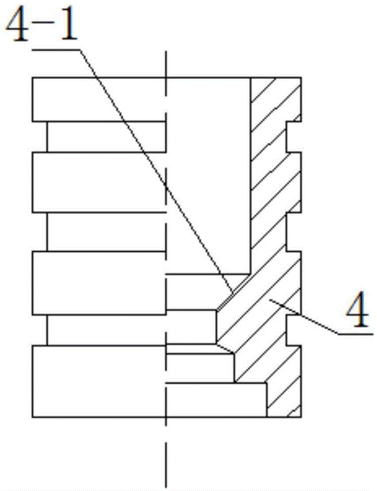
[0023] like figure 1 , figure 2 , image 3 , Figure 4 and Figure 5 As shown, a continuous jarring tool includes an upper joint 1, a jacket 2 with a middle hole, a piston 4, a shuttle key 12, a plunger 11, a sliding sleeve 7 with a middle hole, and a lower joint 9. 2 is inserted into the middle hole of the jacket 2, and is threaded and sealed with the top of the jacket 2. The middle part of the upper joint 1 is provided with a flow groove 14 vertically, and a communication groove 14 is opened on the side wall of the flow groove 14. The diversion hole 1-1 of the middle hole of the outer casing 2, the bottom of the upper joint 1 is provided with a tapered groove 1-2, the piston 4 is vertically sealed in the midd...


PUM


Abstract

The invention relates to a shocking tool, and specifically relates to a continuous shocking tool. The continuous shocking tool comprises an upper joint, an outer sleeve equipped with a medium hole, a piston, a shuttle key, an inserting rod, a sliding sleeve equipped with another medium hole, and a lower joint; the upper joint is inserted from the middle part of the sleeve into the central hole of the outer sleeve; a flowing groove is vertically formed in the top part of the upper joint; a guide hole which communicates with the central hole in the outer sleeve is formed in the sidewall of the flowing groove; a tapered groove is formed in the bottom part of the upper joint; the piston is vertically sealed and arranged in the central hole of the outer sleeve; the bottom part of the upper joint is inserted into an inner cavity of the piston; a sealing ball is arranged in the inner cavity of the piston; the shuttle key is positioned in the central hole of the outer sleeve; the inserting rod is positioned in the central hole of the outer sleeve; a bulge is fixedly arranged on the inner wall of the outer sleeve and below the shuttle key; a compression spring is arranged between the bulge and the base; the sliding sleeve is inserted from the bottom part of the outer sleeve into the outer sleeve; the lower joint passes through the central hole of the sliding sleeve from the bottom part of the sliding sleeve; one end of the lower joint, passing through the sliding sleeve is fixedly connected with the bottom part of the inserting rod. The continuous shocking tool has the beneficial effects of being good in shocking effect and high in shocking efficiency.

Description

technical field [0001] The invention relates to a jarring device, in particular to a continuous jarring tool. Background technique [0002] With the development of downhole operation technology, when using drill pipe or coiled tubing for deep well or large horizontal well operation, there will be insufficient uplift force or downforce, resulting in failure to reach the predetermined depth or to achieve the expected action, especially in fishing operations , For the stuck fish, it is necessary to apply sufficient lifting force or continuous shocking action to achieve the effect of releasing the stuck fish. At present, after one shock with conventional jars, it is necessary to lift up or lower the pipe string to reset it before performing the second shock. While the shock effect is not good, the operating pipe string needs to be lifted up and down repeatedly, not only The vibration efficiency is reduced, and it is also easy to cause damage to the operating pipe string due to ...

Claims


Application Information

Patent Timeline
Patent Type & Authority Applications(China)
IPC IPC(8): E21B31/107
CPCE21B31/113
Inventor 孟凡超韩滔张博浩
Owner JEREH ENERGY SERVICES
Learn More