Trenchless prop

A non-excavation, pipe jacking technology, applied in the direction of pipeline laying and maintenance, pipes/pipe joints/fittings, mechanical equipment, etc., which can solve the problem of small axial jacking force, reduced axial support force, and prone to bending To avoid torsion and other problems, achieve the effect of maintaining integrity and improving axial jacking force

Inactive Publication Date: 2015-04-29
HANGZHOU YISHIDA IND
View PDF8 Cites 0 Cited by
  • Summary
  • Abstract
  • Description
  • Claims
  • Application Information

AI Technical Summary

Problems solved by technology

[0007] The invention solves the defects that the existing pipe jacking ability is small to bear the axial jacking force, and the pipe jacking process is prone to cracks, and provides a non-excavation pipe jacking, the wall of the pipe jacking pipe is lined with several axial The steel pipe improves the ability of the jacking pipe to withstand the jacking force
[0008] The present invention also solves the problem that the existing pipe jacking is filled with steel pipe sleeves, and the axial support force is reduced when making large-diameter pipe jacking, which is prone to bending and torsion defects. It provides a non-excavation pipe jacking with steel pipe support in the pipe wall , it can also have a large axial support force when making large-diameter pipe jacking

Method used


Image

  • Trenchless prop
  • Trenchless prop
  • Trenchless prop

Examples


Embodiment 1

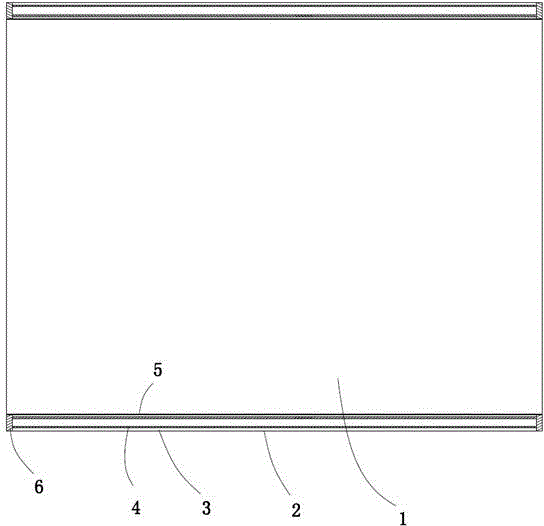
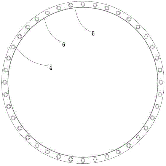
[0028] Embodiment 1: a kind of non-excavation pipe jacking (see attached figure 1 attached figure 2 attached image 3 ), the top pipe is circular, including the inner wall 5, the outer wall 2 and the filler 3 between the inner wall and the outer wall. The two ends of the pipe jacking are provided with closing plates 6, and a plurality of steel pipes 4 are connected between the closing plates, and the ends of the steel pipes are welded and fixed to the surface of the closing plates. The filler is filled outside the steel pipe, the axis of the steel pipe is parallel to the axis of the pipe jacking, and the steel pipes are evenly arranged in the wall of the pipe jacking.

[0029] The closing plate is annular, and the outer diameter of the closing plate is consistent with the outer diameter of the pipe jacking. The inner wall of the jacking pipe extends to the inner ring surface of the closing plate, the ends of the steel pipes are fixed to the closing plate, and the steel pip...

Embodiment 2

[0031] Embodiment 2: a kind of non-excavation pipe jacking (see attached Figure 4 ), the difference from Example 1 is that the steel pipe and the surface of the closed panel are welded and fixed, the steel pipe is arranged along the position where the pipe wall of the jacking pipe is deflected to the inner wall, and the appearance of the steel pipe is tangent to the inner arc edge of the closed plate. Refer to Example 1 for all the other structures.

Embodiment 3

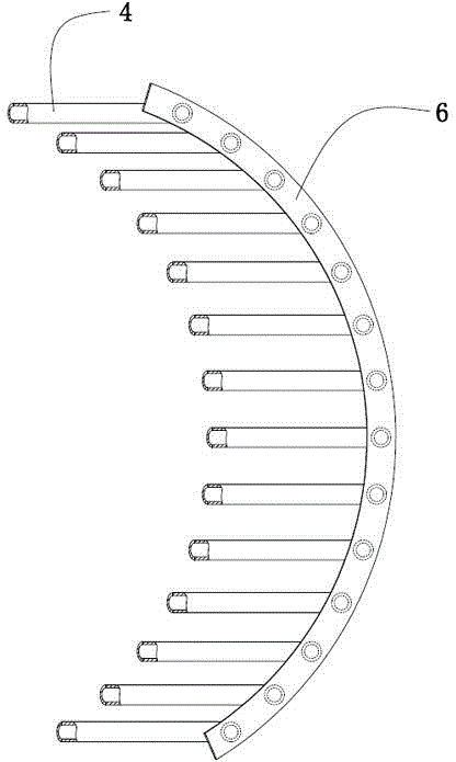
[0032] Embodiment 3: a kind of non-excavation pipe jacking (see attached Figure 5 ), the closed plate at one end of the jacking pipe is formed by butting two semi-closed plates 7, the two semi-closed plates are symmetrical to each other, and the ends of the two semi-closed plates are butted and fixed to form a complete closed plate. The end of the steel pipe is fixed with the semi-closed plate to form a support frame, and the two support frames are combined to form an integral axial support frame for pipe jacking. Refer to Example 1 for all the other structures.


PUM


Abstract

The invention relates to a trenchless prop, and aims to overcome the defect that the prop cracks easily during jack-in since the capacity of the existing prop for bearing axial jacking force is small. The prop comprises an inner wall, an outer wall and filler between the inner wall and the outer wall, wherein the two ends of the prop are provided with sealing plates; a plurality of steel pipes are connected between the sealing plates; the filler is filled on the outer side of the steel pipe; the axis of the steel pipe is parallel to the axis of the prop. The steel pipes can bear the maximum axial acting force, so the axial jacking force of the prop can be improved without causing the problem of jacking collapse; the axial jacking force is born by the steel pipes, and the axial jacking force stressed by the filler is relatively small, so that the integrity of the inner wall and the outer wall of the filler can be kept.

Description

technical field [0001] The invention relates to a pipe structure, in particular to a trenchless pipe jacking. Background technique [0002] In pipeline laying construction, there are generally two methods: [0003] One is the open large-scale excavation method, which is to dig all the ground to form pipe grooves, connect the pipes to each other and place them in the pipe grooves, and then re-lay the soil to fill them up. The effect of the force, that is to say, the pipeline laid by this excavation method does not need to consider the limitation of the jacking force, and the construction is relatively simple and convenient. [0004] Another way is that due to the limitation of the construction location and environment, such as buildings, etc., it is not possible to use large excavation methods to lay pipelines, but to use the method of jacking pipelines into the soil section by section, that is, pre-dig a working pit. When working in the working pit, the pipeline is pushed ...

Claims


Application Information

Patent Timeline
Patent Type & Authority Applications(China)
IPC IPC(8): F16L1/028F16L1/06
CPCF16L1/028F16L1/06
Inventor 丁永明卢希然
Owner HANGZHOU YISHIDA IND
Why Eureka
Try Eureka