A combined waste heat recovery device and waste heat recovery method for high-temperature solid materials

A waste heat recovery device and waste heat recovery technology, which are applied in the field of waste heat recovery devices for direct heat recovery, can solve the problems that waste heat recovery devices cannot meet the direct recovery of high-temperature solid physical heat, and achieve the effect of smooth flow and high-efficiency waste heat recovery

Inactive Publication Date: 2016-08-24
CENT IRON & STEEL RES INST
View PDF6 Cites 0 Cited by
  • Summary
  • Abstract
  • Description
  • Claims
  • Application Information

AI Technical Summary

Problems solved by technology

[0003] One of the objectives of the present invention is to provide a combined waste heat recovery device that can fully recover the physical heat in granular or powdery high-temperature solid materials, which can solve the problem that conventional waste heat recovery devices cannot directly recover high-temperature solid physical heat Problems or high-temperature solid-state physical heat must be heat-exchanged with fluid once and then through the heated fluid for secondary heat-exchange to achieve waste heat recovery

Method used


Image

  • A combined waste heat recovery device and waste heat recovery method for high-temperature solid materials
  • A combined waste heat recovery device and waste heat recovery method for high-temperature solid materials
  • A combined waste heat recovery device and waste heat recovery method for high-temperature solid materials

Examples


Embodiment Construction

[0045] The specific embodiments of the present invention will be further described below in conjunction with the accompanying drawings, and the present invention is not limited to the following examples.

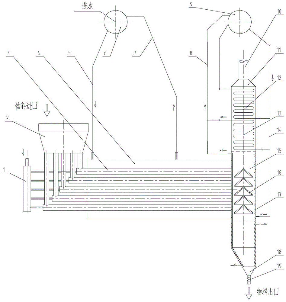
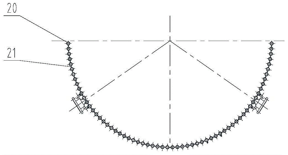
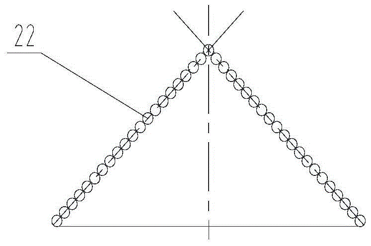
[0046] figure 1 It is a flow chart of the combined high-temperature solid material waste heat recovery device according to the present invention; figure 2 yes figure 1 Schematic diagram of the structure of the evaporative-cooled film wall and water-cooled film wall of the device in ; image 3 yes figure 1 Schematic diagram of the structure of the evaporative cooling deflector in the device.

[0047] The combined waste heat recovery device for high-temperature solid materials (granular or powder) of the present invention fully recovers the heat in the high-temperature solid materials as much as possible to generate steam and utilizes it. It includes two units: the first unit is a horizontal Pneumatic conveying solid-gas-liquid waste heat recovery unit; the second unit is...


PUM


Abstract

The invention relates to the waste heat recovery field of high temperature solid materials, and particularly relates to a waste heat recovery device and a waste heat recovery method of combined high-temperature solid materials. The waste heat recovery device of the combined high-temperature solid materials comprises two units, wherein the first unit is a horizontal pneumatic transmission type solid-gas-liquid waste heat recovery unit, and the second unit is an integral vertical waste heat recovery unit; the first unit comprises a compressed air source (1), a PM (Particulate Matter) stock bin (2), a plurality of pneumatic conveying pipelines (3) driven by the compressed air source (1) and a horizontal pressure tank (4); the second unit comprises a vertical box body (11); feeding holes of the vertical box body (11) are hermetically connected with the outlets of the pneumatic conveying pipelines (3); the upper part of the vertical box body (11) is provided with a heat exchange pipe bundle structure, the middle part of the vertical box body (11) is provided with an evaporation freezing mask type wall structure, and the lower part of the vertical box body (11) is provided with a water cooling membrane type wall structure. According to the waste heat recovery device provided by the invention, physical heat in the high temperature PM can be recovered basically and completely, and the use ratio of steam can be improved greatly.

Description

technical field [0001] The invention relates to the field of waste heat recovery of high-temperature solid materials suitable for various industries such as metallurgy, chemical industry, and building materials, and in particular to a waste heat recovery device and a waste heat recovery method for directly recovering heat in high-temperature solid materials. Background technique [0002] At present, most of the waste heat recovery of high-temperature material particles is in a non-recovery state. The usual waste heat boiler uses cold air as the heat exchange medium to indirectly transfer the physical heat in the high-temperature material to water, thereby generating hot water or steam for production or domestic use. , this method has two major defects. One is that the heat transfer is indirect heat transfer, and the heat transfer efficiency is very low; It is difficult to utilize it again. If the cooling air volume is too large, the cooling rate is improved, but the structur...

Claims


Application Information

Patent Timeline
Patent Type & Authority Patents(China)
IPC IPC(8): F22B1/02
Inventor 贾志立黄芳王晋元胡砚斌侯中晓何赛
Owner CENT IRON & STEEL RES INST
Why Eureka
Try Eureka