Bottom surface crack detection device for concrete bridge

A detection device and concrete technology, which is applied in the direction of optical testing for flaws/defects, etc., can solve problems such as difficulty in ensuring the quality of collected images, limited scope of application, and low precision of cracks, and achieve reliable performance, simple and fast installation, and low cost. Effect

Inactive Publication Date: 2015-04-29
CHINA NUCLEAR IND HUATAI CONSTR
View PDF9 Cites 29 Cited by
  • Summary
  • Abstract
  • Description
  • Claims
  • Application Information

AI Technical Summary

Problems solved by technology

On the one hand, the above methods are difficult to guarantee the quality of the collected images, and the accuracy of the cracks that can be detected is not high. In addition, the above methods have disadvantages such as limited scope of application and high cost.

Method used


Image

  • Bottom surface crack detection device for concrete bridge
  • Bottom surface crack detection device for concrete bridge

Examples


Embodiment Construction

[0021] The invention is further described in combination with the following examples.

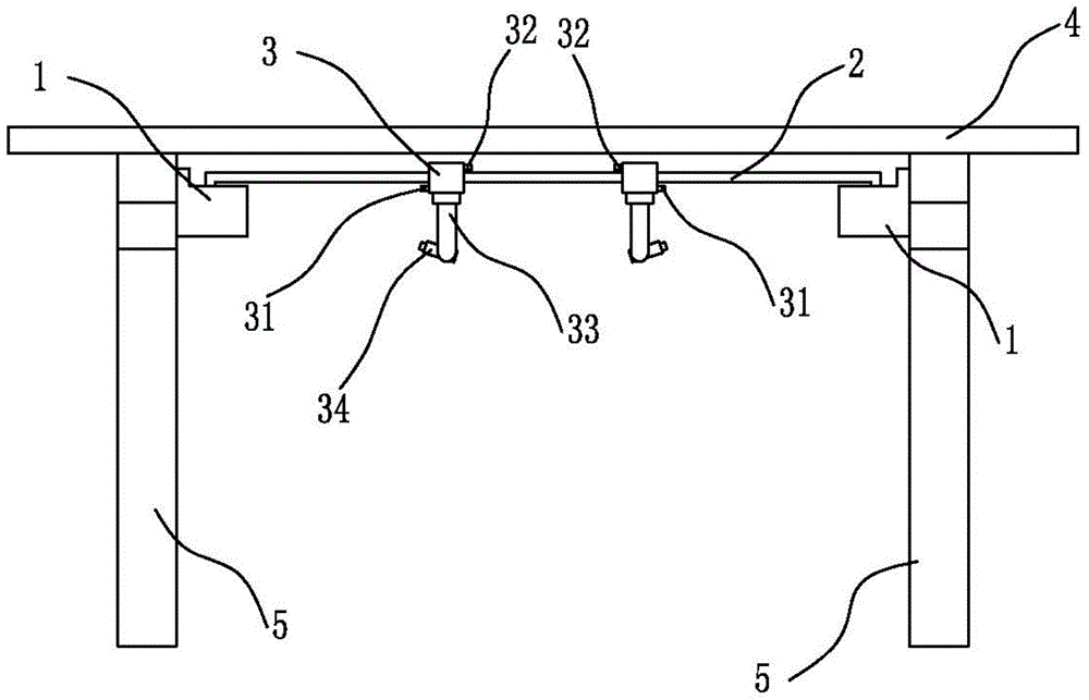
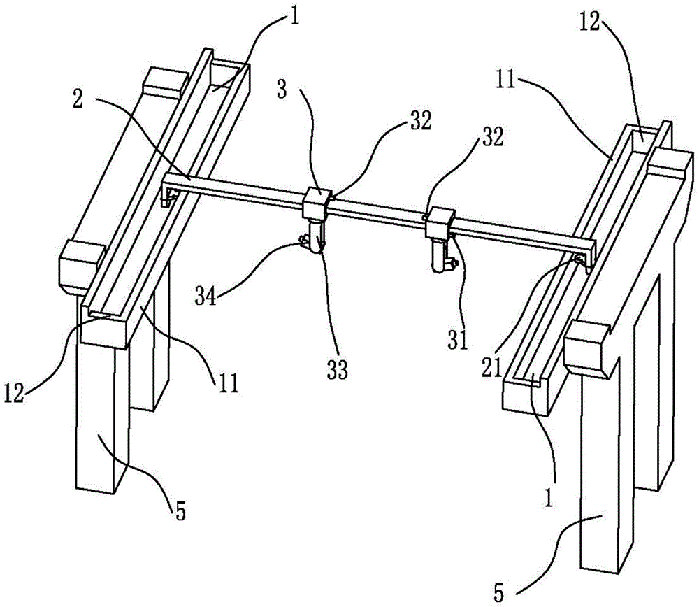
[0022] The invention creates a device for detecting cracks on the bottom surface of a concrete bridge, such as figure 1 with figure 2 As shown, it includes two parallel rail brackets 1, one rail 2, two camera equipment 3, wireless transmission equipment and monitoring equipment.

[0023] reference figure 1 with figure 2 , Two guide rail brackets are arranged between two adjacent bridge piers 4, transversely parallel to the bottom surface of the bridge. The guide rail 2 is vertically arranged between the two guide rail supports 1 and can move along the guide rail support 1. Both ends of the guide rail support 1 are provided with limit parts 12 to restrict the guide rail 2 and prevent it from going out of the guide rail support 1 during the movement. . Preferably, the guide rail bracket 1 extends to the outside of the bridge 4 and exceeds the edge of the bridge 4 for a short period of time to...


PUM


Abstract

The invention relates to the technical field of bridge detection, and in particular relates to a bottom surface crack detection device for a concrete bridge. The bottom surface crack detection device comprises two parallel guide rail brackets, a guide rail, two pieces of camera equipment, wireless transmission equipment and monitoring equipment, wherein the two guide rail brackets are arranged between two adjacent bridge piers, and are transversely parallel to the bottom surface of the bridge; the guide rail is vertically arranged between the two guide rail brackets, and can move along the guide rail brackets; the two pieces of camera equipment are arranged on the guide rail and can move along the guide rail; first travel switches are respectively arranged between the two pieces of camera equipment and the two guide rail brackets; a second travel switch is arranged between the two pieces of camera equipment; a rotatable bracket is arranged on each camera equipment; a camera capable of swinging up and down is arranged on each bracket, and is used for shooting the bottom surface of the bridge; and the images shot by the cameras are wirelessly transmitted to the monitoring equipment through the wireless transmission equipment. The bottom surface crack detection device for the concrete bridge is economical, efficient and high in accuracy.

Description

Technical field [0001] The invention relates to the technical field of bridge detection, in particular to a crack detection device on the bottom surface of a concrete bridge. Background technique [0002] More than 90% of the damage of concrete bridges is caused by cracks. The concrete components work with cracks. Generally, there is no major harm to the normal use of the structure. They can be allowed to exist. However, some cracks continue to expand under the action of load or external physical and chemical factors, causing concrete carbonization and protection. The layer peels off and forms a mechanical discontinuity inside the bridge, which greatly reduces the load-bearing capacity of the bridge, and even collapse accidents in severe cases. [0003] For the detection of cracks on the bottom surface of concrete bridges, the main detection method at home and abroad is manual detection. Manual detection requires a lot of manpower and material resources, and there are often human...

Claims


Application Information

Patent Timeline
Patent Type & Authority Applications(China)
IPC IPC(8): G01N21/88
Inventor 张国刚吕军
Owner CHINA NUCLEAR IND HUATAI CONSTR
Why Eureka
Try Eureka