
PEEC-based electromagnetic screen effect simulation method of case with coupling

A simulation method and electromagnetic simulation technology, applied in the direction of electrical digital data processing, special data processing applications, instruments, etc., can solve problems such as inability to correctly reflect contributions

Active Publication Date: 2015-04-29
XIDIAN UNIV
View PDF2 Cites 4 Cited by
  • Summary
  • Abstract
  • Description
  • Claims
  • Application Information

AI Technical Summary

Problems solved by technology

[0007] The purpose of the present invention is to overcome the "active structure" with radiation effect in the prior art that produces secondary radiation in the internal space of the chassis, which has a strong radiation effect, and the traditional simplified method cannot correctly reflect the radiation effect of the structure contribution to the field strength, while there is currently no methodological problem dealing with this structure

Method used


Image

  • PEEC-based electromagnetic screen effect simulation method of case with coupling
  • PEEC-based electromagnetic screen effect simulation method of case with coupling
  • PEEC-based electromagnetic screen effect simulation method of case with coupling

Examples


Embodiment 1

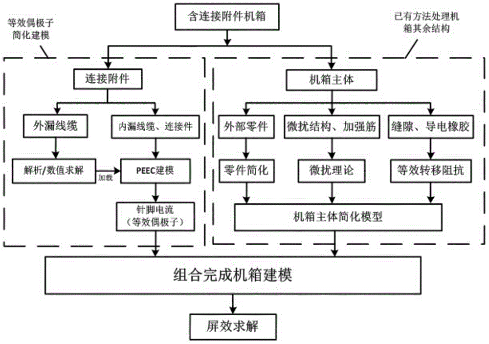
[0042] a kind of like figure 1 As shown, the PEEC-based simulation method for the electromagnetic screen effect of the chassis with connection accessories includes the following steps:

[0043] Step 101, divide the chassis containing the connection accessories into two sub-domains: the chassis main body and the connection accessories;

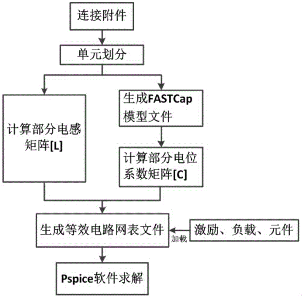
[0044] Step 102, for different sub-domains and objects, based on their characteristics in the electromagnetic compatibility analysis, using different modeling simplification methods to establish electromagnetic simulation numerical models of each part;

[0045] Step 103, after establishing the electromagnetic compatibility analysis numerical models of the connecting accessories and the chassis main body through step 102, combine the complete chassis electromagnetic simulation model, the combination principle is:

[0046] Z ni m ⇔ ...

Embodiment 2

[0067] 1. Simulation object

[0068] select as Figure 4 The shown case model is used for electromagnetic screen effect simulation, in which the shape and structure parameters are L×W×H=400mm×312mm×325mm, and the cable diameter is 1mm, which is located inside the shielded box Ω 1 The length of the cable is l 1 =10mm, outside the shielded box Ω 2 The length of the cable is l 2 =490mm. The GJB599 series 7-pin plug JY2476T11F99P-H, which is common in national defense and aerospace electronic products, is located in the center of the front panel, and the diameter of the conductive copper core is 1.1mm. The 10mm×10mm×10mm metal perturbation structure is located at the corner as shown in the figure, the rib width c=10mm, the thickness is 5mm, and the ventilation hole array is located as Figure 4 The position shown is 25mm away from both sides, and is composed of a 6*6 circular hole array with a diameter of 4mm and an interval of 2mm. The observation point P(100,150,85) is loc...


PUM


Abstract

The invention belongs to the technical field of electromagnetic compatibility of cases, specifically relates to a PEEC-based electromagnetic screen effect simulation method of a case with a coupling, and aims at solving the problem that an active structure with the radiation effect generates secondary radiation in the inner space of the case in the prior art, and relatively high radiation effect is caused, the contribution of the radiation effect of the structure to the field strength cannot be accurately reflected by the traditional simplifying method, and no method is provided for treating such structure at present. The PEEC-based electromagnetic screen effect simulation method of the case with the coupling is characterized in that an equivalent dipole model is built for the coupling; the radiation effect of the coupling can be accurately described on the basis of the simplifying of micro structures such as pins of the coupling, and therefore, the electromagnetic compatibility analyzing mode of the case is accurate; the coupling simplifying method is introduced on the basis of the simplified case electromagnetic model in the original technology, so as to further simplify the compatibility value model of the case, and as a result, the number of grid division is decreased, and the calculation time is reduced.

Description

technical field [0001] The invention belongs to the technical field of chassis electromagnetic compatibility, and in particular relates to a method for emulating the electromagnetic screen effect of a chassis containing connection accessories based on PEEC. Background technique [0002] The electromagnetic field simulation analysis and prediction technology developed in recent years is the basis of the electromagnetic compatibility design of the chassis, which enables the research and development personnel to predict the electromagnetic compatibility characteristics of the chassis at the early stage of design, so as to guide the design. [0003] By installing conductive rubber in the gaps of electronic equipment and using liquid cooling instead of air-cooling heat dissipation holes, etc., the problem of electrical continuity of the shielding layer is better solved, and the screen efficiency of the chassis is improved. However, as the interconnection structure of electronic a...

Claims


Application Information

Patent Timeline
Patent Type & Authority Applications(China)
IPC IPC(8): G06F17/50
Inventor 杨福荣李鹏段宝岩李勋王朝斌
Owner XIDIAN UNIV
Learn More