Smooth switching control method for operating mode of micro-grid inverter of different capacity micro sources
A technology of operation mode and control method, which is applied in the direction of single-network parallel feeding arrangement, energy industry, electrical components, etc., can solve the problems of smooth switching, in-depth and full elaboration, and achieve fast dynamic response, reduce circulation, and stability sex high effect
- Summary
- Abstract
- Description
- Claims
- Application Information
AI Technical Summary
Benefits of technology
Problems solved by technology
Method used
Image
Examples
Embodiment 1
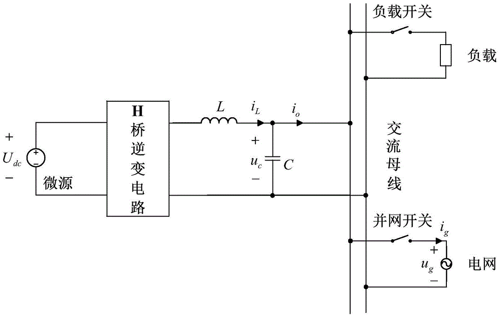
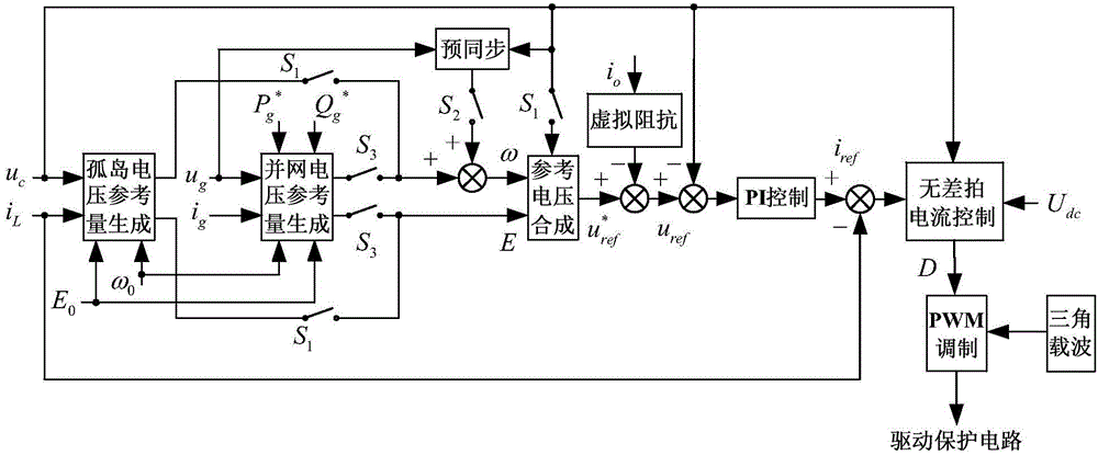
[0075] A control method for smoothly switching operation modes of micro-source micro-grid inverters with different capacities. The method operates in a micro-grid composed of several micro-sources with different capacities. The micro-grid includes several distributed power generation units, and the distributed power generation unit It includes a micro-source connected in sequence, an H-bridge inverter circuit, and an LC filter circuit. The LC filter circuit is connected to an AC busbar through a connecting line, the AC busbar is connected to a load, and is also connected to the power grid. The specific steps include:
[0076] (1) The load switch is closed, and the island operation switch S 1 Closed, the inverter starts the island operation mode;
[0077] (2) The load switch is disconnected, and the island operation switch S 1 disconnected, the presynchronized switch S 2 and grid-connected operation switch S 3 Closed, the grid-connected switch is closed, and pre-synchronizat...
Embodiment 2
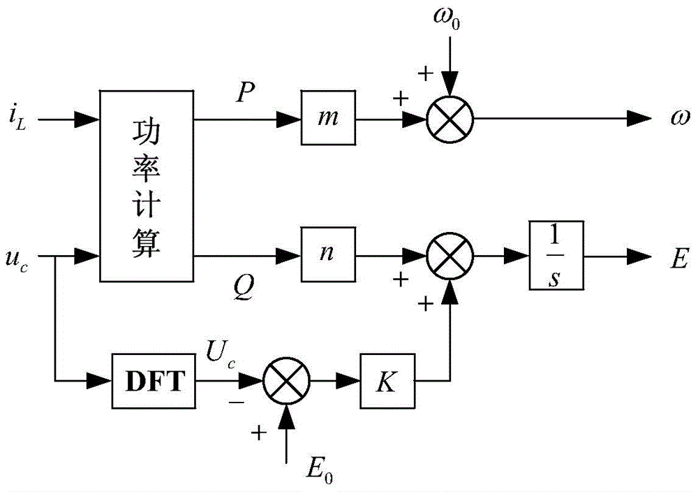
[0083] According to the smooth switching control method described in Embodiment 1, it is further defined as, in step (1), the load switch is closed, and the island operation switch S 1 Closed, the inverter starts the island operation mode, the operation control method of the micro-source micro-grid inverter with different capacities in the island operation mode, the specific control process includes:
[0084] a. According to the filter capacitor voltage u c , filter inductor current i L , to calculate the active power P and reactive power Q in the island operation mode, the calculation formula is as follows:
[0085] P = 1 N Σ k = 1 N u c ...
Embodiment 3
[0100] According to the smooth switching control method described in Embodiment 1, it is further defined that in step (2), during pre-synchronization control, the calculation step of the reference voltage angular frequency ω is:
[0101] h, to grid voltage u g , filter capacitor voltage u c Carry out frequency detection separately to obtain grid voltage angular frequency ω grid and filter capacitor voltage angular frequency ω inv ;
[0102] i. Grid voltage angular frequency ω grid and filter capacitor voltage angular frequency ω inv The difference is adjusted and controlled by PI to get Δω synch :
[0103] Δω synch =k pω (ω grid -ω inv )+k iω ∫(ω grid -ω inv )dt
[0104] Among them, k pω is the proportional coefficient of PI adjustment, k iω Integral coefficient adjusted for PI;
[0105] j. According to grid voltage u g , Grid-connected current i g , to calculate the active power P in grid-connected operation mode g and reactive power Q g :
[0106] ...
PUM
 Abstract
Description
Claims
Application Information
 - R&D
- Intellectual Property
- Life Sciences
- Materials
- Tech Scout
- Unparalleled Data Quality
- Higher Quality Content
- 60% Fewer Hallucinations
Browse by: Latest US Patents, China's latest patents, Technical Efficacy Thesaurus, Application Domain, Technology Topic, Popular Technical Reports.
© 2025 PatSnap. All rights reserved.Legal|Privacy policy|Modern Slavery Act Transparency Statement|Sitemap|About US| Contact US: help@patsnap.com


