
Motor with rotor cooled

A rotor and motor shaft technology, applied in the field of motor rotor cooling, can solve the problems of increased rotor temperature, decreased bearing service life, and high temperature at the bearing, so as to reduce weight and bearing burden, reduce temperature rise, and increase heat dissipation area. Effect

Inactive Publication Date: 2015-04-29
TIANJIN SANTROLL ELECTRIC AUTOMOBILE TECH CO LTD
View PDF0 Cites 19 Cited by
  • Summary
  • Abstract
  • Description
  • Claims
  • Application Information

AI Technical Summary

Benefits of technology

This new method described in the current version allows for better performance compared to existing designs while reducing its size without adding extra parts or requiring more space on top. It also improves cooling efficiency due to improved thermal conduction from the rotating part inside it instead relying solely upon convective airflow through channels within the housing itself rather than utilizing forced circulations like fans that require power input during operation.

Problems solved by technology

This technical problem addressed in this patents relates to improving the efficiency and effectiveness of motor design while reducing its size without sacrificializing their reliability. Current solutions involve adding extra parts like oil lubricants into the motor's case housing, making maintenance difficult when necessary. There also exist other ways to reduce friction losses caused by the rotation of the magnet within the motor itself, including using special coatings made of thermally resistant material instead of grease. These techniques aim to enhance heat transmission coefficients and prevent overheat buildup during operation.

Method used


Image

  • Motor with rotor cooled
  • Motor with rotor cooled

Examples


Embodiment Construction

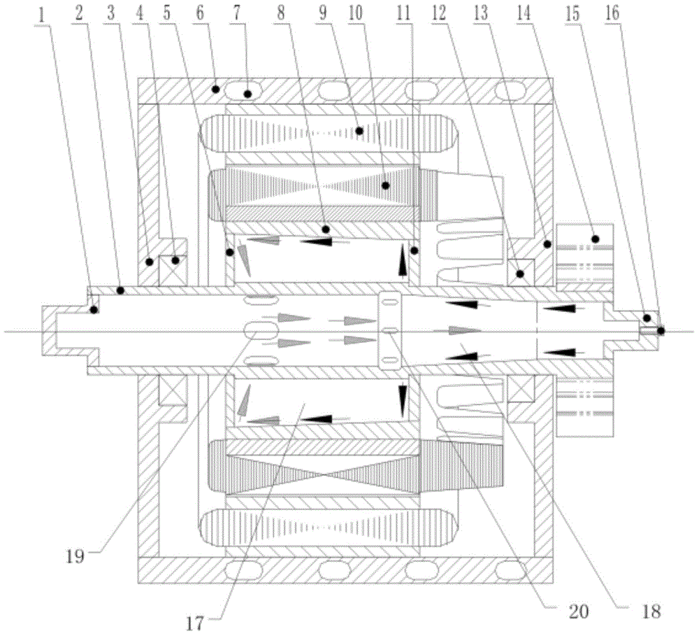
[0018] The technical scheme of the present invention will be further elaborated below in conjunction with the accompanying drawings. Such as figure 1 As shown, the rotor heat dissipation motor is composed of a stator assembly 9, a rotor assembly 10, a casing 6, a front end cover 3, and a rear end cover 13. The rotor assembly 10 can rotate relative to the stator assembly 9; The front bearing 4 and the rear bearing 12 at the center of the cover 3 , the rear end cover 13 are fixedly arranged with the rotor assembly 10 . A bracket is provided between the motor shaft 2 and the rotor assembly 10 to support the rotor. The motor may be a DC permanent magnet, AC asynchronous or switched reluctance motor, and if it is a permanent magnet motor, the above-mentioned rotor assembly is a permanent magnet fixed on a bracket. Wherein, a large amount of heat generated by the stator assembly 9 when the motor is in operation is discharged through the cooling channel 7 arranged on the casing.

...


PUM


Abstract

The invention relates to a motor with a rotor cooled. The motor comprises a stator and the rotor, the rotor is fixedly mounted to a motor shaft through a support, and a sealed support cavity is formed between the rotor and the motor shaft through the support. The motor with the rotor cooled is characterized in that the motor shaft is also provided with a cavity, the support cavity is communicated with the motor shaft cavity, and the motor shaft cavity is filled with phase change heat transfer media. According to the motor with the rotor cooled, the rotor and the rotating shaft are combined to form a heat tube structure, heat generated by the rotor during work is smoothly transmitted to a motor end cooler to be dissipated, and the temperature rise of the rotor is lowered greatly.

Description


Claims


Application Information

Patent Timeline
Owner TIANJIN SANTROLL ELECTRIC AUTOMOBILE TECH CO LTD
Learn More