High-power-factor low-ripple single-stage correcting circuit

A high power factor, correction circuit technology, applied in the direction of output power conversion devices, high-efficiency power electronic conversion, electrical components, etc., can solve the problems of large number of components used, high output ripple current, complex circuit structure, etc., to achieve The effect of reducing the number of uses, reducing the output ripple current, and simplifying the circuit structure

Inactive Publication Date: 2015-04-29
付文贺
View PDF4 Cites 1 Cited by
  • Summary
  • Abstract
  • Description
  • Claims
  • Application Information

AI Technical Summary

Problems solved by technology

[0003] The invention provides a single-stage correction circuit with high power factor and low ripple, which overcomes the problems of low power factor, hig...

Method used


Image

  • High-power-factor low-ripple single-stage correcting circuit
  • High-power-factor low-ripple single-stage correcting circuit

Examples


Embodiment Construction

[0021] The present invention will be further described below in conjunction with the accompanying drawings and preferred embodiments of the present invention.

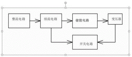
[0022] Such as figure 1 As shown, a single-stage correction circuit with high power factor and low ripple of the present invention includes a rectifier circuit, a freewheeling circuit, an energy storage circuit, a switch circuit and a transformer, and a freewheeling circuit is connected between the rectifier circuit and the energy storage circuit, The freewheeling circuit and the transformer share a switching circuit, and the energy storage circuit adopts a series charging and parallel discharging structure.

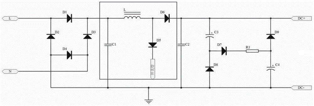
[0023] Such as figure 2 As shown, the rectifier circuit is formed by connecting diodes D1, D2, D3 and D4. The freewheeling circuit includes an energy storage inductor L, a diode D5, a diode D6 and a capacitor C1. The energy storage circuit is composed of capacitors C3, C4, diodes D7, D8, D9 and resistor R1. ...


PUM


Abstract

The invention provides a high-power-factor low-ripple single-stage correcting circuit which comprises a rectifier circuit, a free-wheeling circuit, an energy storage circuit, a switching circuit and a transformer, wherein the free-wheeling circuit is connected between the rectifier circuit and the energy storage circuit; the free-wheeling circuit and the transformer share the switching circuit; the energy storage circuit adopts a series-charging and parallel-discharging structure. The input power factor of the circuit is increased, the output ripple current is reduced effectively, and less components are used, so that the light stroboscopic effect is reduced, the circuit structure is simplified, and the product cost is reduced.

Description

technical field [0001] The invention relates to a single-stage correction circuit, in particular to a single-stage correction circuit with high power factor and low ripple. Background technique [0002] Existing LED drivers usually use flyback or buck topologies, which have the advantages of simple structure and low cost. Good constant current effects can be obtained through primary side feedback, but the power factor is low. Using the valley filling circuit can only achieve a power factor of 0.9, which cannot meet the requirements. Usually integrated power factor correction (PFC) is used to improve the power factor of the line, but the result is that the output current ripple current is large, the response of the feedback loop is slow, and the output light of the lamp has a stroboscopic effect, resulting in power factor and ripple. The bottleneck problem that wave current cannot have both. In order to improve the power factor and reduce the ripple current, a relatively r...

Claims


Application Information

Patent Timeline
IPC IPC(8): H02M3/07H02M1/42H02M1/14
CPCH02M1/14H02M1/4216Y02B70/10
Inventor 付文贺
Owner 付文贺
Why Eureka
Try Eureka