Automatic control method for burst luminous power

A technology of transmitting power and power, which is applied in electromagnetic wave transmission systems, electrical components, transmission systems, etc., and can solve the problems of inability to measure short data packets and ultra-short data packets, and short light-emitting time.

Active Publication Date: 2015-04-29
WUHAN TELECOMM DEVICES
View PDF4 Cites 5 Cited by
  • Summary
  • Abstract
  • Description
  • Claims
  • Application Information

AI Technical Summary

Problems solved by technology

[0003] The purpose of the embodiments of the present invention is to provide a method for automatic control of burst optical power to s

Method used


Image

  • Automatic control method for burst luminous power
  • Automatic control method for burst luminous power
  • Automatic control method for burst luminous power

Examples


Embodiment 1

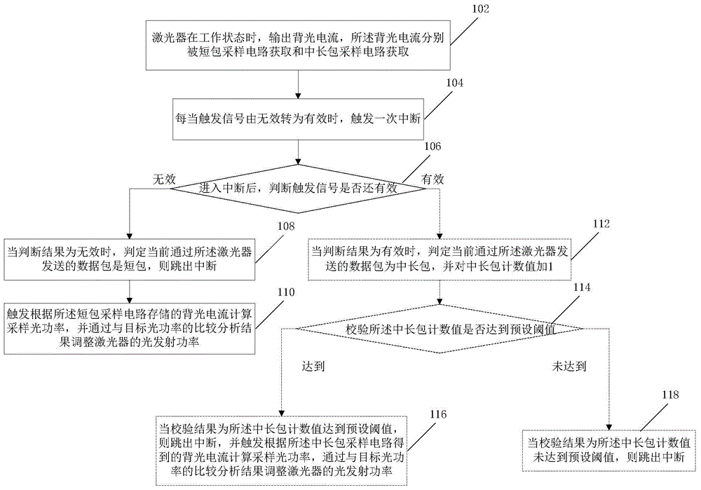
[0022] Such as figure 1 Shown is a flow chart of a method for automatic control of burst optical power provided by the present invention, the laser works within the validity period of the trigger signal, and the method includes the following steps:

[0023] In step 102, when the laser is in the working state, the backlight current is output, and the backlight current is obtained by the short packet sampling circuit and the medium and long packet sampling circuit respectively, wherein the short packet sampling circuit can sample and hold the backlight current at the current moment .

[0024] Wherein, the short-packet sampling circuit and the medium-long-packet sampling circuit may be circuits composed of independent electrical devices, or may be implemented based on internal circuits in an integrated chip (for example: MAX3643 or MCU), which are not specifically limited here.

[0025] In a specific implementation manner, the simplest implementation manner of the medium and lon...

Embodiment 2

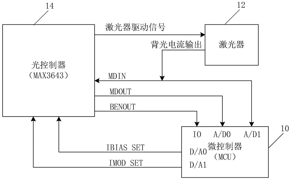
[0053] Such as figure 2 Shown is a schematic structural diagram of a system for automatic control of burst optical power provided by an embodiment of the present invention. figure 2 It can be seen that a system for automatic control of burst optical power provided by the present invention includes an optical driver 14, a microcontroller 10 and a laser 12, the optical driver 14 is used to control the operation of the laser 12, and the microcontroller 10 is used for calculating And adjust the optical power controlled by the laser driver 14, the optical driver 14 generates a trigger signal to control the work of the laser 12, and the system specifically includes in realizing the method of the present invention:

[0054] The laser 12 works within the valid period of the trigger signal, and outputs a backlight current; the backlight current is input to the short packet sampling circuit of the optical driver 14 for storage, and is used to calculate the sampling optical power of th...

Embodiment 3

[0071] Such as figure 2 As shown, this embodiment provides a schematic structural diagram of a system for automatic control of burst optical power, as shown in figure 2 As shown, this embodiment will combine figure 2 The relevant pins of the specific optical driver 14 (MAX3643) and the corresponding pins of the microcontroller 10 (MCU) are used to illustrate this specific implementation. Compared with Embodiment 2, the corresponding system module functions of this embodiment are as follows:

[0072] The laser 12 works within the valid period of the trigger signal, which is specifically a high-frequency BURST-ENABLEIN (abbreviated as: BUSIN), and is carried in the laser driving signal sent by the optical driver 14 to the laser 12 .

[0073] When the laser 12 is working, it outputs backlight current. The optical power of the backlight is proportional to the optical power of the light emitted from the front of the laser, therefore, the optical power of the light emitted by ...


PUM


Abstract

The invention is applied to the field of luminous power control, and provides an automatic control method for burst luminous power. The automatic control method comprises the following steps: when a laser is in a working state, outputting backlight current which is respectively obtained by a short packet sampling circuit and a medium-long packet sampling circuit, wherein the short packet sampling circuit can sample and maintain the backlight current at the current moment; when a trigger signal is turned into being valid from being invalid, triggering interruption for one time; in the interruption process, judging whether the trigger signal is valid or not; if the trigger signal is determined to be invalid, judging that the data packet transmitted by the laser is a short packet, then jumping out of interruption, triggering computing of the sampled luminous power according to the backlight current stored by the short packet sampling circuit, and adjusting the light transmitting power of the laser according to the comparative analysis result with the targeted luminous power. According to the automatic control method disclosed by the invention, the short time storage characteristic of the short packet sampling circuit is utilized, and the short packet current is stored, so that the problem that in the prior art the short packet luminous power adjustment cannot be processed can be solved.

Description

technical field [0001] The invention belongs to the field of optical power control, in particular to a method for automatic control of burst optical power. Background technique [0002] Optical power automatic control is to adjust the bias current and modulation current by comparing the difference between the laser backlight current and the target current, so that the backlight current changes in the direction of the target value. Therefore, the premise of adjusting the optical power is to accurately measure the magnitude of the current backlight current. Burst transmission is transmitted in units of data packets, and the trigger signal (English name: Burst Enable, abbreviated as: BEN) is used as the trigger signal. Therefore, the detection of the burst optical power is to be able to accurately measure the optical power state when the laser performs a burst. At present, the ONU optical module has a solution for the measurement of burst optical power when bursting long data...

Claims


Application Information

Patent Timeline
IPC IPC(8): H04B10/564
Inventor 皮文博陈龙张军张凯曾娜武超群
Owner WUHAN TELECOMM DEVICES
Why Eureka
Try Eureka