Wireless LED lamp control circuit

A technology of LED lamps and control circuits, which is applied in the direction of lamp circuit layout, circuit devices, battery circuit devices, etc., can solve problems such as single function and limited range of use, and achieve the effect of convenient charging

Active Publication Date: 2015-04-29
SHENZHEN ZHONGFUNENG ELECTRIC EQUIPMENG CO LTD
View PDF6 Cites 8 Cited by
  • Summary
  • Abstract
  • Description
  • Claims
  • Application Information

AI Technical Summary

Problems solved by technology

[0002] Cordless LEDs are generally used for outdoor and indoor lighting. The control circuit includes a main control circuit, an LED drive circuit connected to the main control circuit, a battery charging circuit, a battery protection circuit and other basic circuits. The purpose is to charge the LED lamp, And drive LED lights to emit light, the existing LED lights can only provide daily lighting, the function is relatively single, and the scope of use is limited

Method used


Image

  • Wireless LED lamp control circuit
  • Wireless LED lamp control circuit
  • Wireless LED lamp control circuit

Examples


Embodiment Construction

[0026] The present invention will be further described below in conjunction with the accompanying drawings and embodiments.

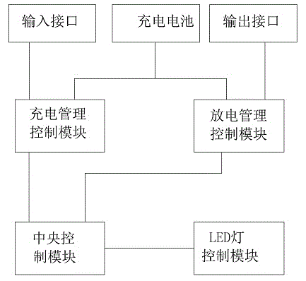
[0027] The first principle block diagram of the embodiment of the cordless LED lamp control circuit of the present invention can be found in figure 1 , including central control module, charge management control module, discharge management control module, LED light control module, rechargeable battery, power input interface and LED light; the central control module is connected with charge management control module, discharge management control module and LED light control module respectively Connection; the output end of the LED light control module is connected to an LED light, and the charging management control module is connected to the power input interface and the rechargeable battery respectively; the discharge management control module is connected to the rechargeable battery, and the output end of the discharge management control module is con...


PUM


Abstract

The invention provides a wireless LED lamp control circuit. A central control module is connected with a charging management and control module and an LED lamp control module respectively, the output end of the LED lamp control module is connected with an LED lamp, the charging management and control module is connected with a power source input interface and a rechargeable battery respectively. The wireless LED lamp control circuit further comprises a discharging management and control module, the discharging management and control module is connected with the central control module and the rechargeable battery respectively, and the output end of the discharging management and control module is connected with a power source output interface. Since the wireless LED control circuit is provided with the discharging management control module and the power source output interface both connected with the central control module, the central control module drives the discharging management and control module to operate when detecting discharging signals, so that the rechargeable battery is discharged, external equipment can be recharged through the power source output interface of the wireless LED lamp, and the wireless LED lamp not only has a lighting function but has a function of a mobile power source.

Description

technical field [0001] The invention relates to an LED control circuit, in particular to a cordless LED lamp control circuit. Background technique [0002] Cordless LEDs are generally used for outdoor and indoor lighting. The control circuit includes a main control circuit, an LED drive circuit connected to the main control circuit, a battery charging circuit, a battery protection circuit and other basic circuits. The purpose is to charge the LED lamp, And drive the LED light to emit light, the existing LED light can only provide daily lighting use, the function is relatively single, and the scope of use is limited. Contents of the invention [0003] The invention provides a cordless LED lamp control circuit, the LED lamp can also provide the function of a mobile power supply in addition to the function of illumination. [0004] In order to solve the above technical problems, the present invention provides a cordless LED lamp control circuit, which includes a central cont...

Claims


Application Information

Patent Timeline
Patent Type & Authority Applications(China)
IPC IPC(8): H05B37/02H02J7/00
Inventor 丁柏平
Owner SHENZHEN ZHONGFUNENG ELECTRIC EQUIPMENG CO LTD
Why Eureka
Try Eureka