
Bending press having an angle-measuring device and method for determining the bending angle

A technology of angle detection and bending machine, which is applied to the bending machine including angle detection device and used to determine the bending angle, can solve the problems of being susceptible to interference, complex structure of measuring equipment, etc., and achieve reliable and simple determination results

Active Publication Date: 2015-04-29
TRUMPF MASCHEN AUSTRIA
View PDF8 Cites 17 Cited by
  • Summary
  • Abstract
  • Description
  • Claims
  • Application Information

AI Technical Summary

Problems solved by technology

[0004] Most of these measuring devices are complex in construction and have a significant susceptibility to interference

Method used


Image

  • Bending press having an angle-measuring device and method for determining the bending angle
  • Bending press having an angle-measuring device and method for determining the bending angle
  • Bending press having an angle-measuring device and method for determining the bending angle

Examples


Embodiment Construction

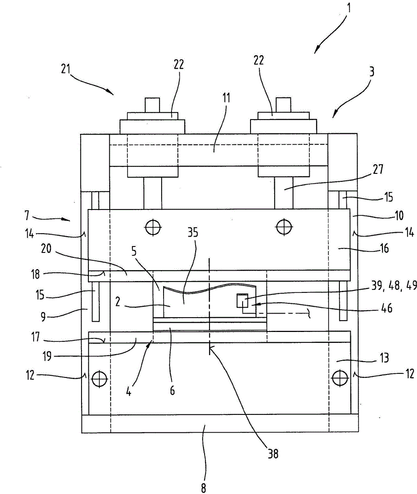
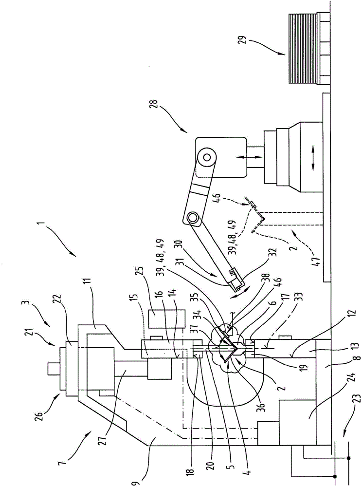
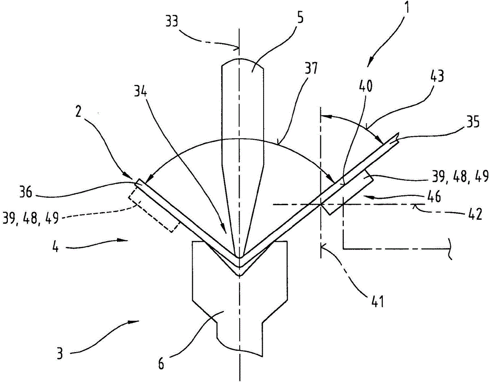
[0048] At the outset, it should be pointed out that the same reference signs or the same component names are used for the same parts in different embodiments, wherein the disclosure contained in the entire description can be transferred to the same components with the same reference signs or the same component names. parts. Likewise, positional indications selected in the description (eg top, bottom, side, etc.) relate to the directly described and illustrated figure and, in the event of a change in position, are automatically transferred to the new position.

[0049] exist figure 1 and figure 2 1 shows a very schematically simplified illustration of a production device 1 , which in this case is designed for free bending of a workpiece 2 to be produced from sheet metal by means of tool bending. However, it is also possible to use a rotary bending machine for carrying out the bending process in the production plant 1 .

[0050] In this case the manufacturing plant 1 used fo...


PUM

PropertyMeasurementUnit
lengthaaaaaaaaaa

Abstract

The invention relates to a production plant (1), in particular for folding workpieces (2) to be produced from sheet metal, comprising a bending press (3), in particular a press brake, having pressing beams (13, 16), at least one bending tool (4), such as a bending punch (5) and a bending die (6), which is connected to the pressing beams (13, 16), and at least one angle-measuring device (46) for determining an angular position of at least one limb (35, 36), formed by a bending operation, of the workpiece (2) with respect to a reference plane (41, 42). In this case, the angle-measuring device (46) comprises at least one inclination sensor (39) which has a reference surface (40) and the inclination sensor (39) having the reference surface (40) is supported by the angle-measuring device (46) so as to be placeable against a surface section of at least one of the limbs (35, 36) of the workpiece (2).

Description

technical field [0001] The invention relates to a manufacturing plant comprising an angle detection device, in particular for bending workpieces to be manufactured from sheet metal, as described in claims 1 and 12, and to a method for determining at least one angle formed by the bending process. method of the angular position of the outrigger with respect to the reference plane. Background technique [0002] A device for measuring angles on a workpiece is known from EP 0 637 371 B1 or from DE 694 11 821 T2, in which a sensor is arranged in the base body of the bending tool which is movable relative to the base body. Each of the sensors has a contact device for contacting the corresponding section of the workpiece during the measurement, wherein the sensors are kinematically completely independent of one another. Furthermore, the device has a separate pressure device in order to bring the contact device of the sensor into contact with the corresponding section of the workpie...

Claims


Application Information

Patent Timeline
Patent Type & Authority Applications(China)
IPC IPC(8): B21D5/02
CPCB21D5/02B21D5/0209B21D5/16G01B5/24G01C9/02B21D5/006
Inventor G·安格雷尔H·伯克K·弗罗伊登塔勒J·加格尔M·赫尔B·施奈德H·施特拉塞尔H·泰斯M·瓦尔德赫尔T·魏斯
Owner TRUMPF MASCHEN AUSTRIA
Learn More