Supercharge Your Innovation With Domain-Expert AI Agents!

Sealing device

A technology for sealing devices and sealing components, which is applied to the sealing of engines, engine components, mechanical equipment, etc., and can solve problems such as reduced sealing performance

Inactive Publication Date: 2015-04-29
EAGLE INDS
View PDF9 Cites 3 Cited by
  • Summary
  • Abstract
  • Description
  • Claims
  • Application Information

AI Technical Summary

Problems solved by technology

Aging of rubber sealing parts will lead to a decrease in sealing performance

Method used


Image

  • Sealing device
  • Sealing device
  • Sealing device

Examples


Embodiment 1

[0069] refer to Figure 1~3 The sealing device according to Embodiment 1 of the present invention will be described.

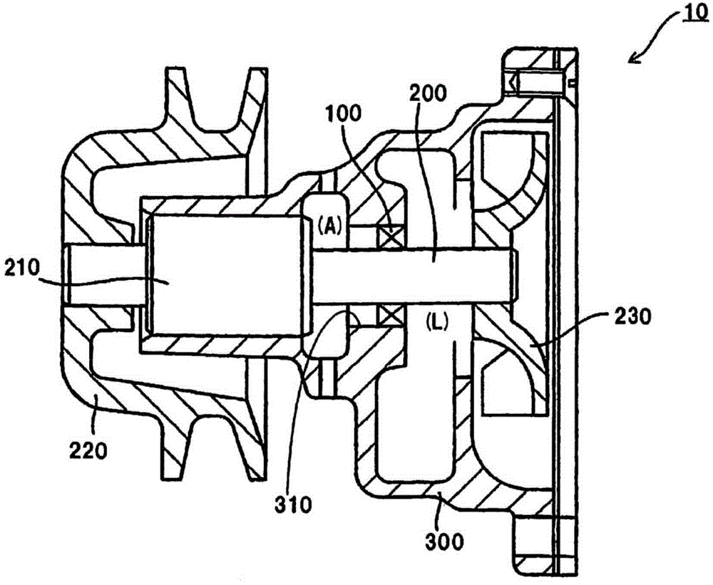
[0070] refer to figure 1 An example of a sealing device according to an embodiment of the present invention will be described. figure 1It is a cross-sectional view showing an example of a sealing device according to an embodiment of the present invention, and is a schematic cross-sectional view of an automotive water pump 10 . The water pump 10 has a rotating shaft 200 and a shaft housing 300 having a shaft hole 310 passing through the rotating shaft 200 . A bearing 210 for smoothly rotating the rotating shaft 200 is installed on the rotating shaft 200 . A pulley 220 is attached to one end of the rotating shaft 200, and the pulley 220 is given rotational driving force by a belt not shown, and an impeller 230 for pressure-feeding cooling water is attached to the other end of the rotating shaft 200. In order to prevent the cooling water from leaking to the o...

Embodiment 2

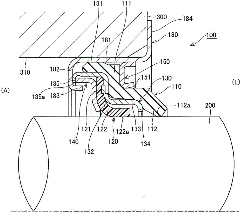
[0098] refer to Figure 4 , Figure 5 , Embodiment 2 of the present invention will be described. Figure 4 It is a cross-sectional view of the use state of the sealing device 100 according to the second embodiment of the present invention. Figure 5 (a) is a perspective view of the sealing device 100 of Embodiment 2 of the present invention, Figure 5 (b) is a side view seen from the atmosphere side (A side).

[0099] In this embodiment, a modified example of the casing in the above-mentioned first embodiment will be described. Since the other configurations and functions are the same as in the first embodiment, the same components are given the same reference numerals and their descriptions are omitted.

[0100]Depending on the relationship between the rotating shaft 200 and the inner diameter of the shaft hole 310 of the shaft housing 300 , there are cases where the annular gap to be sealed by the sealing device 100 becomes large. Therefore, in the sealing device 100 of...

Embodiment 3

[0102] Image 6 Embodiment 3 of the present invention is shown. In this embodiment, a metal sleeve 250 fitted on the outer peripheral surface of the rotating shaft 200 is used. Since the other structures and functions are the same as those in Embodiments 1 and 2, the same components are given the same reference numerals and their descriptions are omitted.

[0103] A sleeve 250 is provided to facilitate the installation of the rotating shaft 200 in the shaft hole 310 of the shaft housing 300 and to protect the outer peripheral surface of the rotating shaft 200 . As the rotating shaft 200 rotates, the sleeve 250 slides on the sliding portion 112 a of the rubber lip 112 and the sliding portion 122 a of the resin lip 122 and rotates. That is, in the present invention, the sliding portion 112a of the rubber lip 112 and the sliding portion 122a of the resin lip 122 are not limited to directly sliding on the outer peripheral surface of the rotating shaft 200, but may also slide on ...


PUM


Abstract

The objective of the present invention is to reduce the deterioration of sealing efficiency caused by heat, generated by a resin seal member sliding on a rotary shaft, conveyed to a rubber seal member. A sealing device comprises a rubber seal member (110), a resin seal member (120), a support ring (130), and a case (180). The support ring (130) has: a large diameter section (131); an inward flange (135) that extends radially inward from the edge on the air side of the large diameter section (131) and contacts an inward flange (182) of the case (180), and that has a notch (135a) into which a claw (183) is fit; a small diameter section (133) that is coupled, via a step portion (132), to the edge on the sealing fluid side of the large diameter section (131), contacts the inner circumferential face of a lip section (112) of the rubber seal member (110), and extends further than a sliding portion (122a) on the sealing fluid side; and a lip support (134) that extends radially inward from the edge on the sealing fluid side of the small diameter section (133).

Description

technical field [0001] The invention relates to a sealing device which seals an annular gap between a rotating shaft and a shaft housing having a shaft hole passing through the rotating shaft. Background technique [0002] Conventionally, sealing devices such as those shown in Patent Documents 1 and 2 are known. The sealing device in the prior art example disclosed in Patent Document 1 will now be described. The sealing device disclosed in Patent Document 1 is installed on the inner peripheral surface of the shaft hole of the shaft housing, and seals the annular gap between the shaft and the shaft housing having the shaft hole passing through the shaft. The sealing device has a metal case, and each component of the sealing device is fixed by the case to integrally form a bush. This sealing device includes a rubber sealing member (hereinafter referred to as rubber sealing member) as a primary seal, and a resin member (hereinafter referred to as resin sealing member) that ma...

Claims


Application Information

Patent Timeline
IPC IPC(8): F16J15/32
CPCF16J15/322F16J15/3232F16J15/324F16J15/002F16J15/3268
Inventor 老山幸一郎中园优作有田泰久
Owner EAGLE INDS
Features
  • R&D
  • Intellectual Property
  • Life Sciences
  • Materials
  • Tech Scout
  • Unparalleled Data Quality
  • Higher Quality Content
  • 60% Fewer Hallucinations
Learn More