
A tapping jig

A wire clamp and screw technology, which is applied in the field of machining, can solve the problems that the force of the workpiece cannot be effectively dispersed, it is difficult to control the tightening force, and the tapping direction is inclined. The effect of dispersing force

Active Publication Date: 2018-01-02
广东法迪奥厨卫科技有限公司
View PDF7 Cites 0 Cited by
  • Summary
  • Abstract
  • Description
  • Claims
  • Application Information

AI Technical Summary

Problems solved by technology

Due to the special material of aluminum profiles, if the existing clamps suitable for plates are used for fixing, since the clamping seat and the workpiece to be clamped are in point-to-point rigid contact, it is difficult to control the tightening force, and it is easy to crush the workpiece
However, manual tapping has the disadvantages of low efficiency and high loss. When tapping, it is easy to tilt the tapping direction due to manual operation, resulting in bad teeth, unilateral teeth and other bad products.
CN103722254A discloses a clip tapping fixture, which overcomes the defects caused by the point contact between the pressing seat and the workpiece, but only one workpiece can be processed at a time, and the efficiency is low
CN102371492A discloses a double-sided tapping fixture. Although it can process two workpieces at the same time, the fixture adopts point contact on one side of the workpiece and surface contact on the other side, so that the force on the workpiece cannot be effectively dispersed, and the workpiece is easily crushed. defect

Method used


Image

  • A tapping jig
  • A tapping jig

Examples


Embodiment Construction

[0035] The present invention is described in further detail below in conjunction with accompanying drawing:

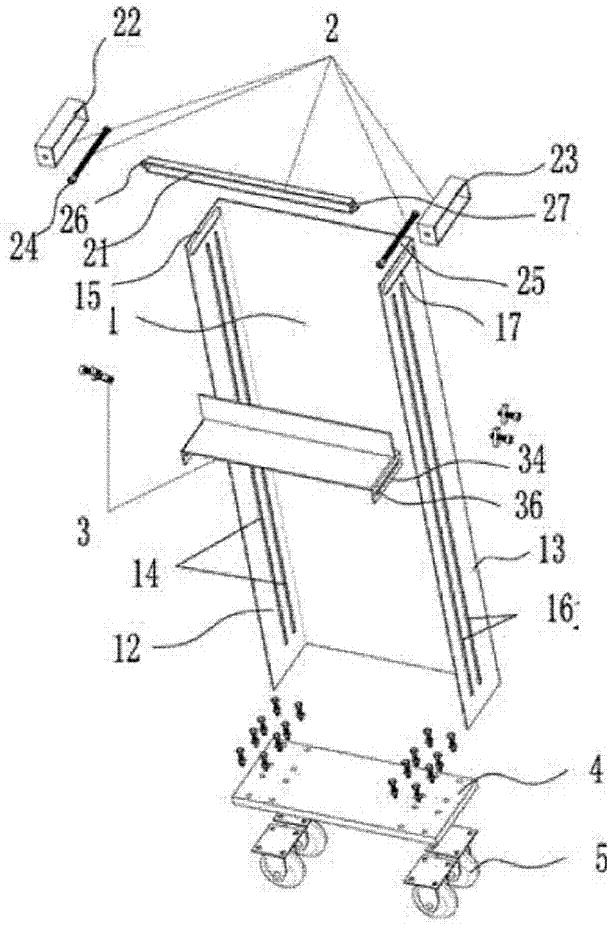
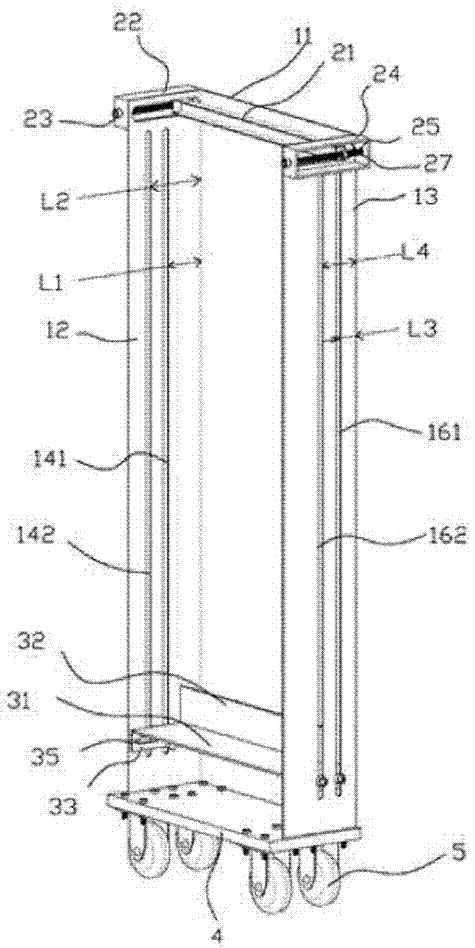
[0036] as attached figure 1 with 2As shown, a tapping fixture includes a U-shaped plate body 1, a compression set 2 for pressing a workpiece, and a support set 3 for supporting the workpiece. The U-shaped plate body 1 is folded from a plate It is formed by bending, including a main board 11, a first side board 12 and a second side board 13. The first side plate 12 is respectively provided with a first fixing part 14 for fixing the supporting set and a first mounting part 15 for installing the pressing set, and the second side plate 13 is respectively provided with a The second fixing part 16 of the supporting sleeve and the second mounting part 17 for installing the pressing sleeve, the first fixing part 14 is two vertical fixing slots respectively the first front slot 141 and the first front slot 141. The first middle groove 142, the second fixing member 15 is two ...


PUM


Abstract

The invention discloses a tapping fixture, which comprises an U-shaped plate body, a pressing sleeve and a support sleeve, wherein the compressing sleeve is arranged on the U-shaped plate body, a first fixing piece and a first mounting piece are arranged on the first side plate, the first fixing piece is used for fixing the support sleeve, the first mounting piece is used for mounting the pressing sleeve, a second fixing piece and a second mounting piece are arranged on the second side plate, the second fixing piece is used for fixing the support sleeve, the second mounting piece is used for mounting the pressing sleeve, and a to-be-tapped workpiece is firmly fixed by the pressing sleeve and the support sleeve. The tapping fixture has the advantages that the tapping fixture is suitable for the batch tapping of end surfaces of shaft and aluminum profile workpieces; the operation is simple, the fixing is firm, the working efficiency is high, and the tapping position is regular.

Description

technical field [0001] The invention belongs to the field of mechanical processing, and in particular relates to a tapping clamp. Background technique [0002] At present, the tapping clamps in the production of machinery industry are generally clamped for flanges and plate products, and this type of clamping is not suitable for shafts and aluminum profiles. In the prior art, shaft workpieces mainly adopt lathe drilling and manual tapping. Due to the special material of aluminum profiles, if the existing clamps suitable for plates are used for fixing, since the clamping seat and the workpiece to be clamped are in point-to-point rigid contact, it is difficult to control the tightening force, and it is easy to crush the workpiece . However, manual tapping has the disadvantages of low efficiency and high loss. When tapping, it is easy to incline the tapping direction due to manual operation, resulting in bad teeth, unilateral teeth and other bad products. CN103722254A disclo...

Claims


Application Information

Patent Timeline
Patent Type & Authority Patents(China)
IPC IPC(8): B23Q3/00B23G1/44
CPCB23G1/44B23Q3/00
Inventor 綦双元邓文阁蔡玉榜施海钊欧阳灿球沈奕荣
Owner 广东法迪奥厨卫科技有限公司
Learn More