A railway funnel driver brake device

A brake device and hand brake technology, which is applied to the railway brake system, railway car body parts, railway vehicle brake operating mechanism, etc., can solve problems such as difficult manufacturing, broken pedals, and complicated bracket structure , to achieve the effect of simple structure and easy manufacture

Active Publication Date: 2017-04-05
CRRC TAIYUAN CO LTD
View PDF7 Cites 0 Cited by
  • Summary
  • Abstract
  • Description
  • Claims
  • Application Information

AI Technical Summary

Problems solved by technology

[0010] It solves the problem that the original railway funnel driver's brake bracket has a complex structure, is difficult to manufacture, and the pedals added at the end beams are damaged during the shunting operation;

Method used


Image

  • A railway funnel driver brake device
  • A railway funnel driver brake device
  • A railway funnel driver brake device

Examples


Embodiment Construction

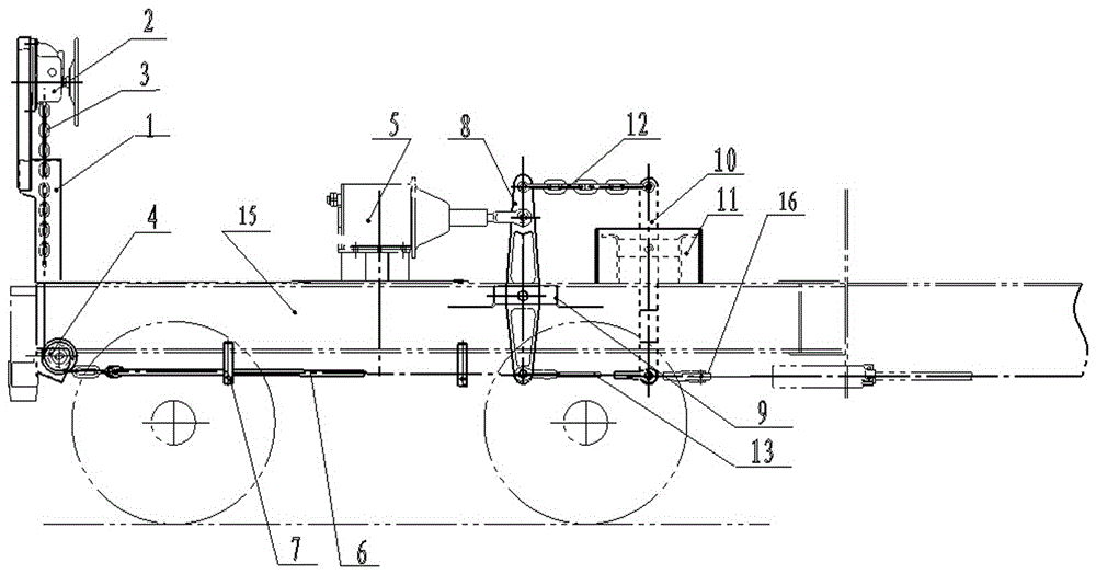
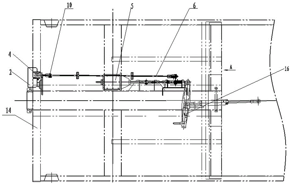
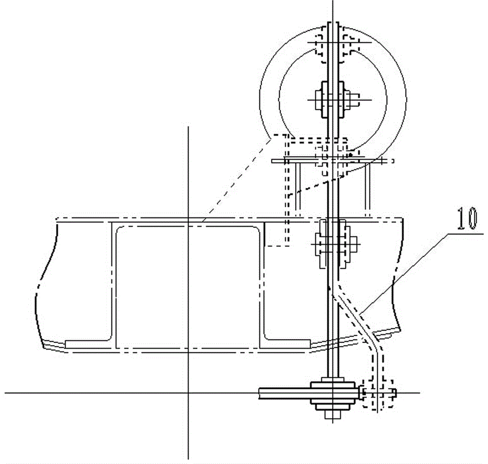
[0053] A railway hopper driver braking device, such as figure 1 , 2 , 3, including hand brake bracket 1, hand brake 2, hand brake chain 3, fixed pulley and support 4, brake cylinder and push rod 5, and hand brake lever 6 And hand brake pull rod guide frame 7, vertical lever 8 and vertical lever fulcrum seat 9, conversion lever 10 and conversion lever fulcrum seat 11, horizontal transmission chain composition 12 and conversion pull rod composition 13,

[0054] The handbrake bracket is fixed vertically on the end beam with sufficient strength and rigidity. The fixed pulley and support are installed on the inside or outside of the end beam 14. The moving pull rod is hung under the bottom frame through the brake rod guide frame, the vertical lever is vertically hinged on the bottom frame through the fulcrum seat of the vertical lever, the fulcrum seat of the conversion lever is fixed on the bottom plate or the traction beam, and the conversion lever is vertically installed on the...


PUM


Abstract

The invention relates to the technical field of a railroad freight car braking, in particular to a railroad hopper car hand braking device which solves a plurality of problems existing in actual application of an existing railroad hopper car. The railroad hopper car hand braking device comprises a hand brake support, a hand brake, a hand brake chain, a fixed pulley, a supporting base, a brake cylinder and a push rod, and further comprises a hand brake pull rod, a hand brake pull rod guide frame, a vertical lever, a vertical lever supporting point base, a switching lever, a switching lever supporting point base, a horizontal transmission chain and a switching pull rod. The hand brake support, the fixed pulley and the supporting base are fixed to an end beam, the hand brake pull rod guide frame and the brake pull rod are installed on the lower portion of a bottom frame, the vertical lever is vertically hinged to the bottom frame, and the lower end of the switching lever extends to the position below the bottom frame. The railroad hopper car hand braking device is arranged below the end beam and the bottom frame, completely eliminates the probability that a supporting frame is pulled out through an existing hopper car hand brake pull rod reinforcing rib and the problem that a hand brake pull rod breaks and influences running safety, and meets the requirement for running safety of the railroad hopper car.

Description

technical field [0001] The invention relates to the technical field of railway freight car braking, in particular to a braking device for railway hopper drivers. Background technique [0002] The hand brake is used to produce a braking effect when the railway vehicle is shunting to prevent the parked vehicle from slipping away. The braking ratio is directly related to whether the vehicle can be parked safely as required. Existing railway hopper cars usually use the hand brake pull rod that drives the pulley device to amplify the manual power magnification and transmit the hand brake force to the foundation brake device. The reinforcement rib of the original hand brake tie rod is assembled and welded by three round steels with a diameter of 16 mm. Due to the sudden change in geometric size, the stress is very concentrated at this place. According to statistics, the cracks and breakage of the original hand brake pull rod reinforcement rib (that is, the welding place of 3 roun...

Claims


Application Information

Patent Timeline
Patent Type & Authority Patents(China)
IPC IPC(8): B61H13/02
CPCB61H13/02
Inventor 李旭英冯永顺哈彩霞常二亮刘文胜谢剑锋马俊峰
Owner CRRC TAIYUAN CO LTD
Why Eureka
Try Eureka