Front auxiliary frame cross reinforcement structure

A technology of front subframe and strengthening structure, applied in the substructure, vehicle parts, transportation and packaging, etc., can solve the problems of weak resistance to lateral impact, poor anti-brake nodding effect, insufficient rigidity of the subframe, etc. The effect of low cost, reduced damage, and improved vehicle ride comfort

Inactive Publication Date: 2015-05-06
ANHUI TECHN COLLEGE OF MECHANICAL & ELECTRICAL ENG
View PDF11 Cites 3 Cited by
  • Summary
  • Abstract
  • Description
  • Claims
  • Application Information

AI Technical Summary

Problems solved by technology

[0003] Since the McPherson suspension is straight, it can bear a large vertical force, but the ability to resist lateral impact is weak, the anti-brake nodding effect is poor, the suspension stiffness is weak, and the turning roll is obvious. As far as the sub-frame is concerned, firstly, the sub-frame needs to have sufficient rigidity and strength to ensure that the car does not deform too much when turning and braking; Under the torsional load, under the action of large bending moment or torque, the insufficient stiffness of the sub-frame will also cause local damage to the structure; thirdly, the sub-frame with low stiffness will reduce the ride comfort of the car during driving

Method used


Image

  • Front auxiliary frame cross reinforcement structure
  • Front auxiliary frame cross reinforcement structure

Examples


Embodiment Construction

[0017] See attached picture:

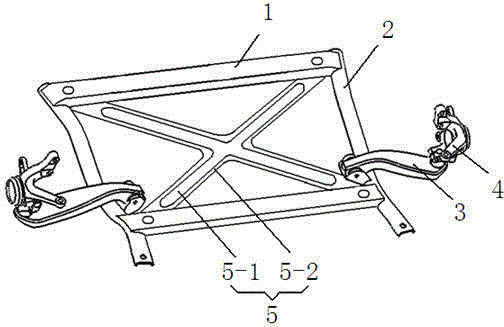
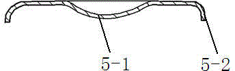
[0018] Front sub-frame cross reinforcement structure, including two front sub-frame longitudinal beams 2 welded and fixed at both ends of two front sub-frame beams 1, two front sub-frame beams 1 and two front sub-frame longitudinal beams 2 Constitute a square frame, two front sub-frame longitudinal beams 2 opposite inner walls are symmetrically hinged and installed with a swing arm 3, and the swing arm 3 is close to the junction of the rear side sub-frame beam 1 and the two front sub-frame longitudinal beams 2 , the upper end surface of the swing arm 3 is fixed with a steering knuckle 4, and an "X"-shaped reinforcement plate 5 is provided under the two front sub-frame beams 1, and the four ends of the reinforcement plate 5 are connected with each corresponding front sub-frame The two ends of the beam are fixed.

[0019] The two front sub-frame beams 1 are hollow rectangular beams, and the two front sub-frame longitudinal beams 2 are hollow cylin...


PUM


Abstract

The invention discloses a front auxiliary frame cross reinforcement structure. The front auxiliary frame cross reinforcement structure comprises two front auxiliary frame longitudinal beams which are welded and fixed to two ends of two front auxiliary frame transverse beams, wherein the two front auxiliary frame transverse beams and the two front auxiliary frame longitudinal beams form a square framework; swinging arms are symmetrically hinged to and mounted on the opposite inner sides of the two front auxiliary frame longitudinal beams; the swinging arms are close to a junction point between the front auxiliary frame transverse beams on the rear sides and the two front auxiliary frame front auxiliary frame longitudinal beams; steering joints are fixed on the upper end surfaces of the swinging arms; X-shaped reinforcing plates are arranged under the two front auxiliary frame longitudinal beams; four ends of each reinforcing plate are fixed to two ends of the corresponding front auxiliary frame transverse beams. According to the front auxiliary frame cross reinforcement structure, an integrated cross reinforcement structure is mounted at four corners of a frame-shaped front auxiliary frame under the condition that arrangement of a power assembly is not influenced, so that the purpose of improving the overall rigidity and strength of the front auxiliary frame is achieved; the reduction of the risk of influence on the automotive performance caused because of insufficient rigidity or strength of the auxiliary frame can be facilitated; meanwhile, the smoothness of the automobiles can be improved.

Description

technical field [0001] The invention relates to the field of automobile manufacturing, in particular to a front subframe cross reinforcement structure. Background technique [0002] Most cars use McPherson suspension as the front suspension type. MacPherson suspension is simple in structure and light in weight. [0003] Since the McPherson suspension is straight, it can bear a large vertical force, but the ability to resist lateral impact is weak, the anti-brake nodding effect is poor, the suspension stiffness is weak, and the turning roll is obvious. As far as the sub-frame is concerned, firstly, the sub-frame needs to have sufficient rigidity and strength to ensure that the car does not deform too much when turning and braking; Under torsional load, under the action of large bending moment or torque, the insufficient stiffness of the sub-frame will also cause local damage to the structure; thirdly, the sub-frame with low stiffness will reduce the ride comfort of the car d...

Claims


Application Information

Patent Timeline
Patent Type & Authority Applications(China)
IPC IPC(8): B62D21/00
CPCB62D21/00B62D21/02
Inventor 倪晋挺杨姝王小龙徐文杰谢承慧魏银花范雅情
Owner ANHUI TECHN COLLEGE OF MECHANICAL & ELECTRICAL ENG
Why Eureka
Try Eureka