AI technical title is built by Patsnap AI team. It summarizes the technical point description of the patent document.
A locking mechanism and container technology, applied in the field of containers, can solve the problems of reduced locking reliability of locks, heavy workload of operators, increased storage costs, etc., to achieve enhanced locking reliability, reduced transportation and storage costs, and compact and compact structure. Effect
Active Publication Date: 2015-05-06
SHANGHAI HONGYAN RETURNABLE TRANSIT PACKAGINGS CO LTD
View PDF6 Cites 34 Cited by
Summary
Abstract
Description
Claims
Application Information
AI Technical Summary
This helps you quickly interpret patents by identifying the three key elements:
Problems solved by technology
Method used
Benefits of technology
Problems solved by technology
This solution reduces the specific operation of locking the side panels and avoids the damage of related parts on the upper cover. However, due to its thick thickness and not being located directly above the side panels, the concave part on the upper cover of the product after folding The groove cannot be well hidden by the structure of the bottom of the box, so that the cumulative height after folding is relatively high, which is not conducive to transportation and increases storage costs. Moreover, when the box is full of liquid, the side panels will expand outward under pressure, which will cause The depth of the lock tongue inserted into the side plate pit becomes shallower, which greatly reduces the reliability of the lock catch
[0005] The above existing technical solutions also have a common defect, that is, when unlocking, it is necessary to run the sides where the two locks are located to unlock respectively, which makes the operator's workload heavy
Method used
Image
Click on the blue label to locate the original text in one second.
Reading with bidirectional positioning of images and text.
Examples
Embodiment 1
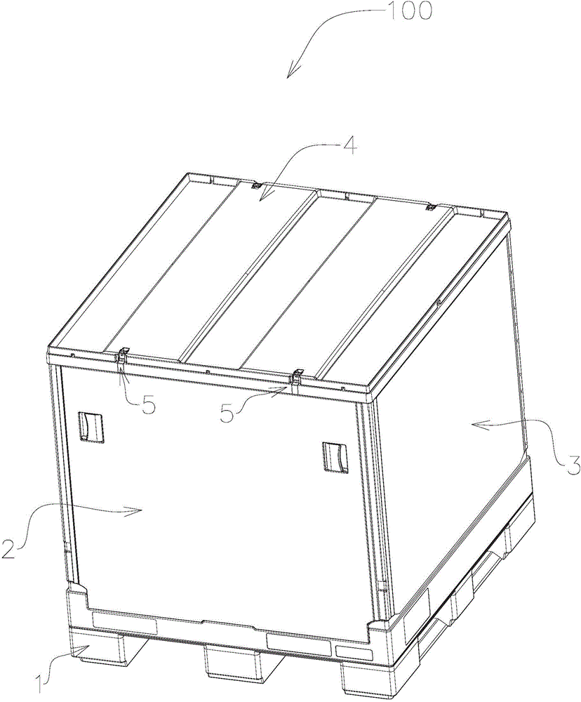
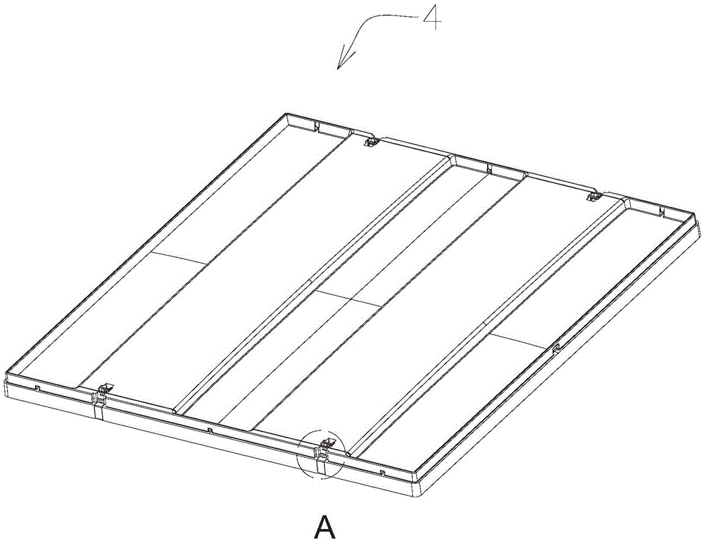
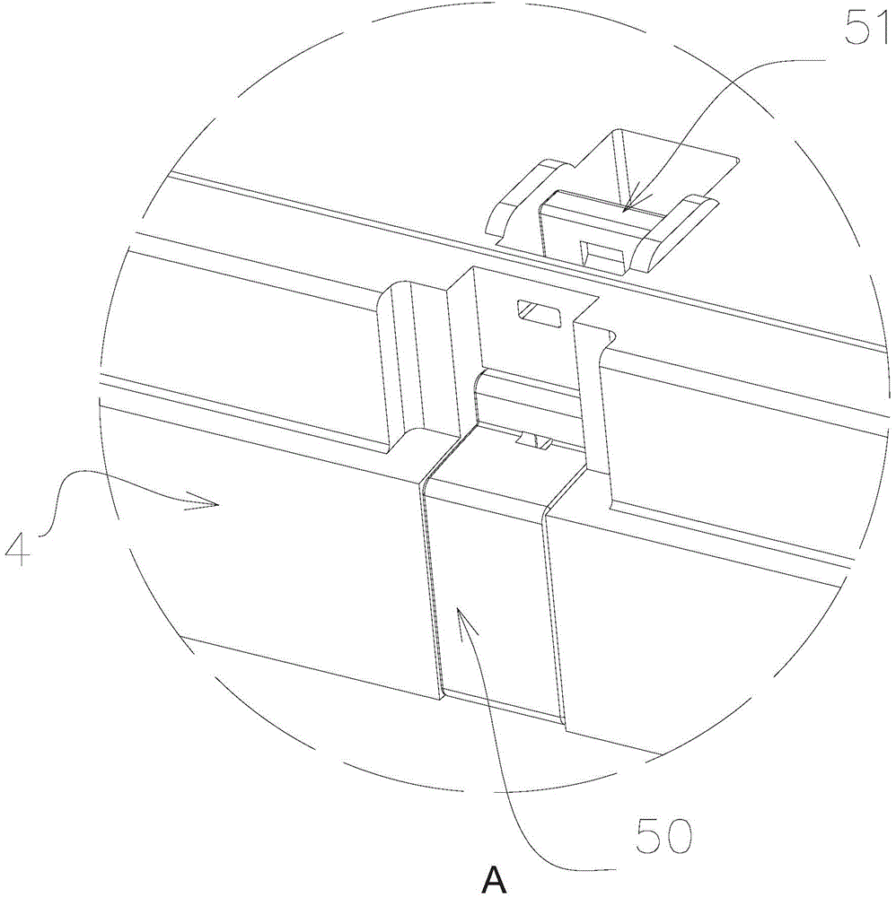
[0059] Such as Figure 1-16 As shown, the container 100 of this embodiment includes a base 1, a pair of opposite side plates 2 and a pair of opposite side plates 3, and an upper cover 4. The locking mechanism 5 includes a locking member 50, a driving member 51, and a locking member 51 formed on the side plates. Side plate structure 52, spring 53 and the upper cover structure 54 formed on the upper cover, locking member 50 and driver 51 are all installed in the upper cover structure 54, when upper cover 4 is installed on the side plate 2, the side plate structure 52 receives a part of the locking member 50 so as to lock the upper cover 4 on the side panel 2 .
[0060] figure 1 It is a three-dimensional view of the container of the present invention. Such as figure 1 As shown, the container 100 includes a base 1 , a pair of opposite side panels 2 , a pair of opposite side panels 3 , and an upper cover 4 . A locking mechanism 5 is provided between the upper cover 4 and the si...
Embodiment 2
[0081] In this embodiment, the parts that are not described in detail are the same as those in Embodiment 1.
[0082] Such as Figures 16-23 As shown, the difference between this embodiment and Embodiment 1 is mainly that the driving member is used to drive the locking member 50 to move through the rotational movement of the driving member.
[0083] Such as Figure 20-22 As shown, the upper cover structure 54 on the upper cover 4 includes a surface portion 54B disposed on the upper surface of the upper cover and a side portion 542 disposed on a side portion of the upper cover. In this embodiment, the side portion 542 of the upper cover is the same as that of Embodiment 1, and will not be described in detail here.
[0084] Such as Figures 16-19 As shown, the surface portion 54B includes a groove 54B1, a rotating shaft 54B2, a rotating shaft hanging platform 54B3, and a hanging platform 54B4. Wherein, the rotating shaft 54B2 is disposed in the groove 54B1, the rotating shaf...
PUM
Abstract
The invention discloses a locking mechanism which is used for locking an upper cover of a container on a container side plate. The container comprises a base, the upper cover and side plates, wherein the upper cover is provided with a safe edge. The locking mechanism comprises a locking piece, a driving piece, a resetting piece, lock holes and a groove, wherein the lock holes are formed in the outer side of at least one side plate, and the groove is formed in the upper cover; one end of the locking piece is arranged in the groove, and the other end of the locking piece is provided with a lock head; the lock head penetrates through the safe edge and can extend into one of the lock holes along a direction vertical to the corresponding side plate, so that the upper cover is locked to the corresponding side plate; the driving piece is arranged in the groove and is used for driving the locking piece to perform unlocking, and the resetting piece is arranged in the groove and is used for resetting the driving piece after unlocking is finished. According to the container and the locking mechanism, the transportation cost and the storage cost can be lowered and the labor intensity of operators is alleviated.
Description
technical field [0001] The invention relates to a container, in particular to a locking mechanism for the container. Background technique [0002] Generally, a large container has four side panels and a bottom, and a large container for transporting liquid or bulk cargo often also has an upper cover to protect the goods loaded inside. There is a ring of guards around the upper cover, which are close to the outer sides of the four side plates of the container. When the goods inside the container exert a large force on the side plates, the guards of the upper cover can protect the side plates from deformation to a certain extent is too big. In addition, when the liquid or bulk goods in the container fluctuate upwards, the upper cover can well limit the ups and downs of the liner bags containing them, thereby also protecting the liner bags from being damaged. This requires that the upper cover can be reliably connected with the box body during use. In addition, most of the f...
Claims
Application Information
Patent Timeline
Application Date:The date an application was filed.
Publication Date:The date a patent or application was officially published.
First Publication Date:The earliest publication date of a patent with the same application number.
Issue Date:Publication date of the patent grant document.
PCT Entry Date:The Entry date of PCT National Phase.
Estimated Expiry Date:The statutory expiry date of a patent right according to the Patent Law, and it is the longest term of protection that the patent right can achieve without the termination of the patent right due to other reasons(Term extension factor has been taken into account ).
Invalid Date:Actual expiry date is based on effective date or publication date of legal transaction data of invalid patent.

