Container and its locking mechanism

A locking mechanism and container technology, applied in the field of containers, can solve the problems of reduced locking reliability, heavy operator workload, increased storage costs, etc., to achieve enhanced locking reliability, reduced transportation and storage costs, and a small and compact structure Effect

Active Publication Date: 2017-06-13
SHANGHAI HONGYAN RETURNABLE TRANSIT PACKAGINGS CO LTD
View PDF1 Cites 0 Cited by
  • Summary
  • Abstract
  • Description
  • Claims
  • Application Information

AI Technical Summary

Problems solved by technology

This solution reduces the specific operation of locking the side panels and avoids the damage of related parts on the upper cover. However, due to its thick thickness and not being located directly above the side panels, the concave part on the upper cover of the product after folding The groove cannot be well hidden by the structure of the bottom of the box, so that the cumulative height after folding is relatively high, which is not conducive to transportation and increases storage costs. Moreover, when the box is full of liquid, the side panels will expand outward under pressure, which will cause The depth of the lock tongue inserted into the side plate pit becomes shallower, which greatly reduces the reliability of the lock catch
[0005] The above existing technical solutions also have a common defect, that is, when unlocking, it is necessary to run the sides where the two locks are located to unlock respectively, which makes the operator's workload heavy

Method used


Image

  • Container and its locking mechanism
  • Container and its locking mechanism
  • Container and its locking mechanism

Examples


Embodiment 1

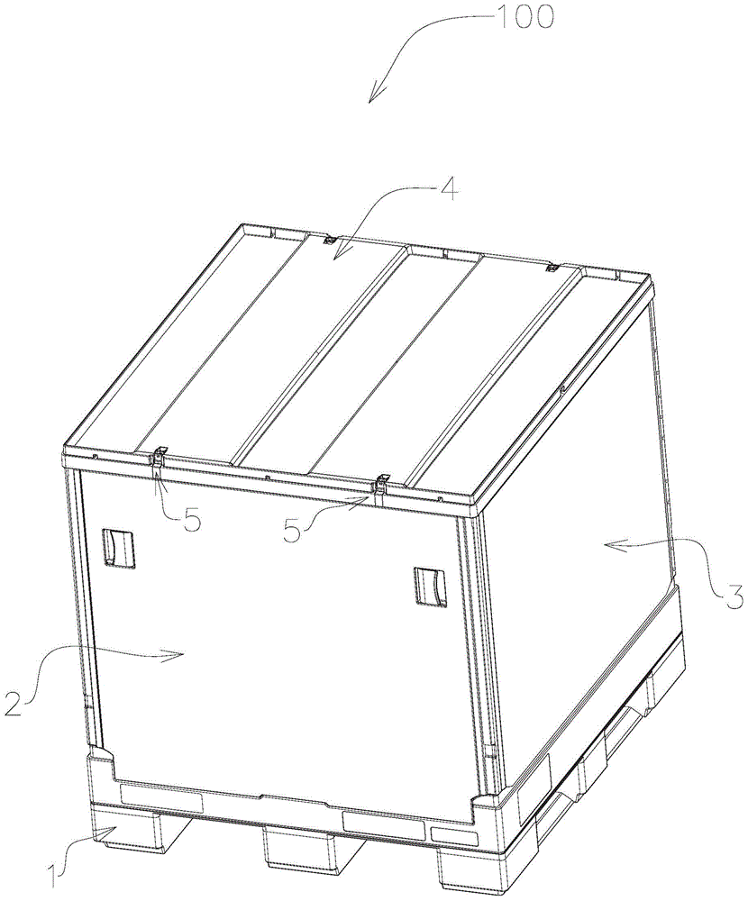
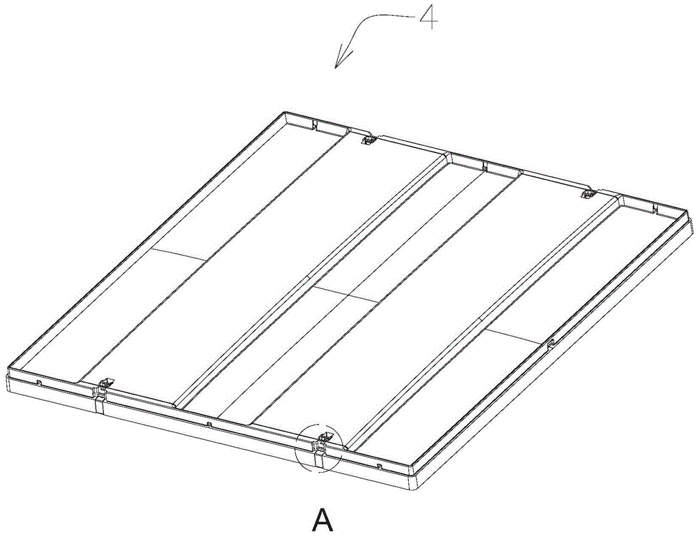
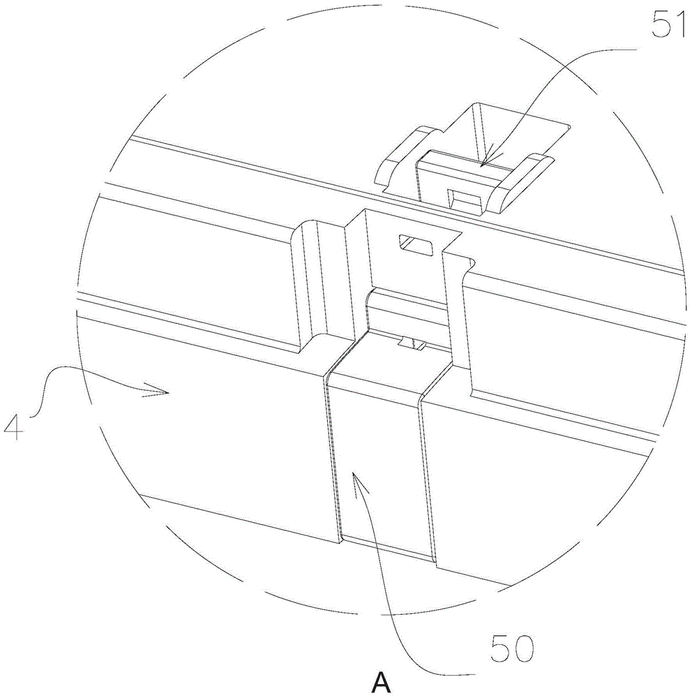
[0059] Such as Figure 1-16 As shown, the container 100 of this embodiment includes a base 1, a pair of opposite side plates 2 and a pair of opposite side plates 3, and an upper cover 4. The locking mechanism 5 includes a locking member 50, a driving member 51, and a locking member 51 formed on the side plates. Side plate structure 52, spring 53 and the upper cover structure 54 formed on the upper cover, locking member 50 and driver 51 are all installed in the upper cover structure 54, when upper cover 4 is installed on the side plate 2, the side plate structure 52 receives a part of the locking member 50 so as to lock the upper cover 4 on the side panel 2 .

[0060] figure 1 It is a three-dimensional view of the container of the present invention. Such as figure 1 As shown, the container 100 includes a base 1 , a pair of opposite side panels 2 , a pair of opposite side panels 3 , and an upper cover 4 . A locking mechanism 5 is provided between the upper cover 4 and the si...

Embodiment 2

[0081] In this embodiment, the parts that are not described in detail are the same as those in Embodiment 1.

[0082] Such as Figures 16-23 As shown, the difference between this embodiment and Embodiment 1 is mainly that the driving member is used to drive the locking member 50 to move through the rotational movement of the driving member.

[0083] Such as Figure 20-22 As shown, the upper cover structure 54 on the upper cover 4 includes a surface portion 54B disposed on the upper surface of the upper cover and a side portion 542 disposed on a side portion of the upper cover. In this embodiment, the side portion 542 of the upper cover is the same as that of Embodiment 1, and will not be described in detail here.

[0084] Such as Figures 16-19 As shown, the surface portion 54B includes a groove 54B1, a rotating shaft 54B2, a rotating shaft hanging platform 54B3, and a hanging platform 54B4. Wherein, the rotating shaft 54B2 is disposed in the groove 54B1, the rotating shaf...


PUM


Abstract

The invention discloses a locking mechanism for locking an upper cover of a container on a side plate of the container. The container comprises a base, an upper cover and a side plate, and the upper cover is provided with a protective edge. The locking mechanism includes a locking piece, a driving piece, a reset piece, a locking hole formed on the outside of at least one side plate and a groove formed on the upper cover, wherein one end of the locking piece is installed in the groove, and the locking piece The other end is provided with a lock head, which passes through the edge protection and can extend into the lock hole in the direction perpendicular to the side plate to lock the upper cover on the side plate, and the driver is installed on the side plate. The groove is used to drive the locking member to unlock, and the reset member is installed in the groove and used to reset the driving member after unlocking. The present invention can reduce the cost of transportation and storage, and reduce the labor of the operator.

Description

technical field [0001] The invention relates to a container, in particular to a locking mechanism for the container. Background technique [0002] Generally, a large container has four side panels and a bottom, and a large container for transporting liquid or bulk cargo often also has an upper cover to protect the goods loaded inside. There is a ring of guards around the upper cover, which are close to the outer sides of the four side plates of the container. When the goods inside the container exert a large force on the side plates, the guards of the upper cover can protect the side plates from deformation to a certain extent is too big. In addition, when the liquid or bulk goods in the container fluctuate upwards, the upper cover can well limit the ups and downs of the liner bags containing them, thereby also protecting the liner bags from being damaged. This requires that the upper cover can be reliably connected with the box body during use. In addition, most of the f...

Claims


Application Information

Patent Timeline
Patent Type & Authority Patents(China)
IPC IPC(8): B65D90/54
CPCB65D90/66B65D2590/666B65D90/54B65D19/18B65D2519/00711B65D19/38B65D45/18B65D45/16B65D55/02
Inventor 不公告发明人
Owner SHANGHAI HONGYAN RETURNABLE TRANSIT PACKAGINGS CO LTD
Why Eureka
Try Eureka