Novel conveying pipeline

A pipeline, a new type of technology, applied in the field of new transmission pipelines, can solve the problems of weak mobility, narrow application range, difficult to change, etc., and achieve the effect of strong reliability and wide application range

Inactive Publication Date: 2015-05-06
张海锋
View PDF6 Cites 1 Cited by
  • Summary
  • Abstract
  • Description
  • Claims
  • Application Information

AI Technical Summary

Problems solved by technology

[0003] Common conveying equipment, such as conveyor belts and conveying rollers on automatic production lines or logistics conveying lines, have strong integrity, but special erection planning is required. It is difficult to change after erection, and the mobility is weak
Moreover, conveyor belts or conveyor rollers use friction to drive products to move, and the magnitude of friction depends on the weight of the goods or products themselves. Therefore, conveyor belts or conveyor rollers in the prior art can only be used for horizontal transportation, and their application range is very narrow.
At the same time, the conveyor belt or the conveyor roller itself can only be used for straight-line transmission. Once the trajectory of the conveyor needs to turn, multiple conveyor belts or conveyor rollers are required.

Method used


Image

  • Novel conveying pipeline
  • Novel conveying pipeline

Examples


Embodiment 1

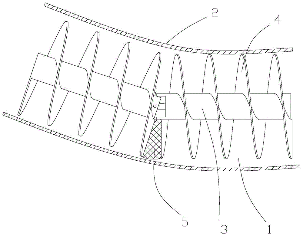
[0028] see figure 1 , this embodiment discloses a new pipeline for transmission, including a pipeline 2, a helical blade rotor core and a motor; the helical blade rotor core is composed of at least one helical blade unit 1 connected, and the helical blade unit 1 includes a central shaft 3 located at the center , the helical blade 4 around the periphery of the central shaft 3, and the universal joint joints located at both ends of the central shaft 3; the two adjacent helical blade units 1 are connected together through the universal joint joint transmission, and the two universal joints The joint joints are combined into a universal joint; the helical blade rotor core is penetrated inside the pipeline 2 and extends along the extension direction of the pipeline 2; the end of the helical blade rotor core is connected with the motor drive.

[0029] Traditional conveying equipment such as conveyor belts can only be used for straight-line conveyance of goods, and the structure of e...

Embodiment 2

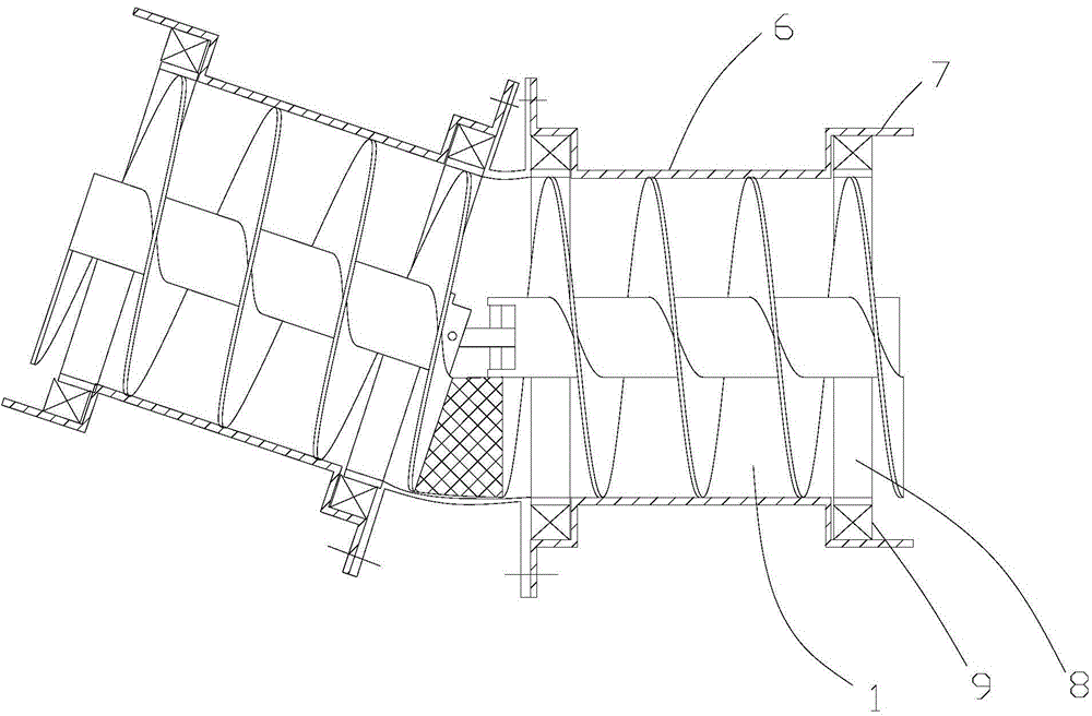
[0040] see figure 2 , The difference between this embodiment and Embodiment 1 is that: on the basis of the solution of Embodiment 1, a bearing 9 is added to increase the stability of the operation of the device. For light load occasions or when the extension length between the pipe 2 and the helical blade rotor core is not long, the running resistance between the helical blade rotor core and the pipe 2 is not large, but in a heavy-load environment, the helical blade rotor core and the pipe 2 The running resistance between them is greatly increased, even if a high-torque motor is used, it may not be able to smoothly promote the rotation of the spiral blade core.

[0041] The technical solutions that can be applied to heavy-duty environments are introduced in detail below:

[0042]Preferably, the helical blades 4 at both ends of the helical blade unit 1 are rigidly connected with an annular bearing connecting portion 8, the inner wall of the bearing connecting portion 8 is flu...


PUM


Abstract

The invention provides a novel conveying pipeline, which comprises a pipeline body, a spiral blade rotary core and a motor, wherein the spiral blade rotary core is formed by connecting at least one spiral blade unit; each spiral blade unit comprises a center shaft, a spiral blade and universal joint connecting parts; each center shaft is arranged in the center part; each spiral blade is arranged around the periphery of the corresponding center shaft; each universal joint connecting part is arranged at two ends of the corresponding center shaft; two adjacent spiral blade units are in transmission connection by the corresponding universal connecting parts; each spiral blade rotary core is arranged in the pipeline body in a penetrating way, and extends along the extending direction of the pipeline body, and the end part of each spiral blade rotary core is in transmission connection with the motor. The novel conveying pipeline has the advantage that goods are pushed by the blade and are conveyed along the pipeline.

Description

technical field [0001] The invention relates to the field of transmission equipment, in particular to a novel transmission pipeline. Background technique [0002] In industry, it is often necessary to transfer goods, products, etc. The purpose is to transfer goods or products from the starting point to the end point through a specific route, eliminating manual handling operations and improving work efficiency. [0003] Common conveying equipment, such as conveyor belts and conveying rollers on automatic production lines or logistics conveying lines, have strong integrity, but special erection planning is required. It is difficult to change after erection, and the mobility is weak. Moreover, the conveyor belt or the conveyor rollers all use friction to drive the product to move, and the magnitude of the friction depends on the weight of the goods or the product itself. Therefore, the conveyor belt or the conveyor roller in the prior art can only be used for horizontal transpo...

Claims


Application Information

Patent Timeline
Patent Type & Authority Applications(China)
IPC IPC(8): B65G33/14
CPCB65G33/14
Inventor 张海锋
Owner 张海锋
Why Eureka
Try Eureka