
Integrated construction method of scaffolding system

A construction method and integrated technology, applied in the field of construction, can solve problems such as low efficiency, poor operability, and missing items in design verification projects, and achieve the effect of ensuring construction safety, lowering thresholds, and avoiding blind spots in bracket design.

Active Publication Date: 2017-03-22
SHANGHAI TUNNEL ENG CO LTD +1
View PDF4 Cites 0 Cited by
  • Summary
  • Abstract
  • Description
  • Claims
  • Application Information

AI Technical Summary

Problems solved by technology

[0005] 1) Poor security: Affected by the geometric shape of the concrete structure, the support system used to carry the structural self-weight during the concrete pouring and maintenance of the structure often does not bear the force in one direction, but bears the combined force in multiple directions at the same time
Therefore, the current calculation method only considers the one-way force of the support system, and there is a problem of missing items in the design check calculation items
[0006] 2) The degree of intelligence is low: the calculation adopts the trial calculation mode, and the design parameters of the bracket are manually determined for checking calculation to determine whether the bracket system is safe
Because the calculation is greatly affected by human factors, the efficiency of its design calculation is low, the degree of intelligence is not enough, and the economy is difficult to achieve optimal
[0007] 3) Poor operability: the design of the support system with a single component as the object will cause the support system of each component to fail to connect well at the interface. On-site operations can only be designed and erected based on experience, and most In the accident case, it is precisely these parts that are at risk first and lead to the collapse of the entire support system

Method used


Image

  • Integrated construction method of scaffolding system
  • Integrated construction method of scaffolding system
  • Integrated construction method of scaffolding system

Examples


Embodiment Construction

[0068] In order to make the object, technical solution and advantages of the present invention clearer, the present invention will be further described in detail below in conjunction with the accompanying drawings and embodiments. It should be understood that the specific embodiments described here are only used to explain the present invention, not to limit the present invention.

[0069] The integrated construction method of the stent system of the present invention includes:

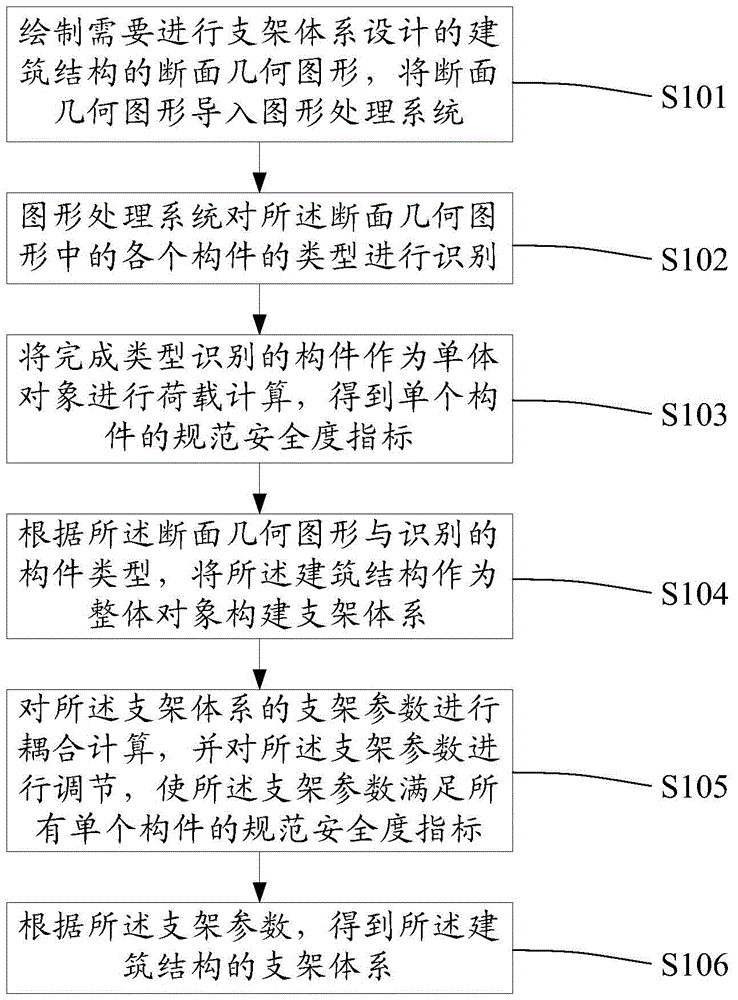
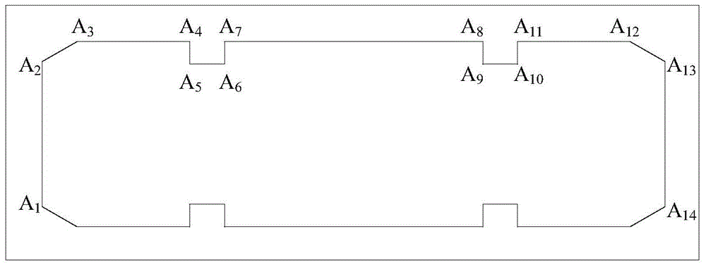
[0070] Draw the cross-sectional geometric figure of the building structure that needs to be designed for the support system, and import the cross-sectional geometric figure into the graphics processing system;

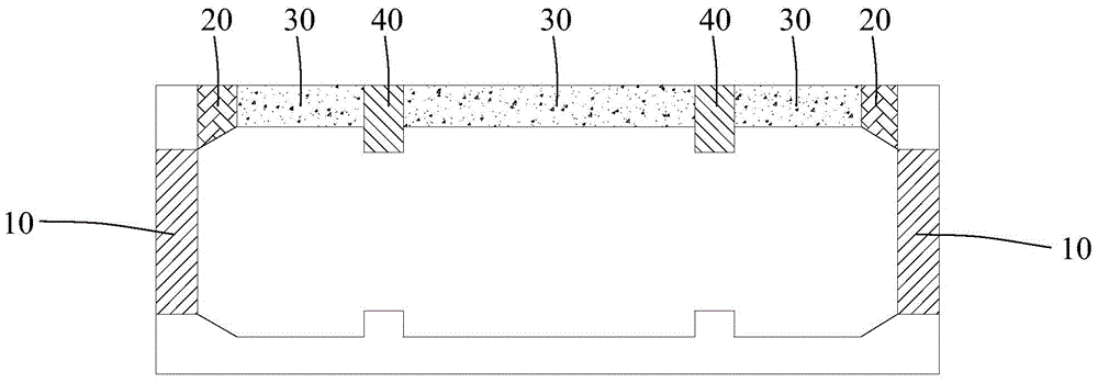
[0071] The graphics processing system identifies the type of each component in the section geometry;

[0072] The component that has completed the type identification is used as a single object for load calculation, and the standard safety index of a single component is obtained;

[0073] Co...


PUM


Abstract

The invention provides an integrated construction method of a support system. The method includes the steps that a section geometric figure of a building structure with the support system design requirement is drawn and input to a figure processing system; the types of components in the section geometric figure are identified through the figure processing system; the loads of the components, with the types identified, serving as individual objects are calculated, so that standard safety degree indexes of the single components are acquired; according to the section geometric figure and the identified component types, the building structure serves as a whole object for establishing the support system; support parameters of the support system are coupled and calculated and adjusted, so that the support parameters meet the standard safety degree indexes of all the single components; according to the support parameters, the support system of the building structure is acquired. By the adoption of the method, the building structure serves as a whole for support design, all the components in different positions and different directions in a whole structure section are comprehensively considered, and therefore the support system can bear the load effect of the different components in different directions.

Description

technical field [0001] The invention relates to the field of building construction, in particular to an integrated construction method of a bracket system. Background technique [0002] As more and more buildings appear in various cities, the number and types of building brackets are also increasing. At present, the most commonly used support systems in my country include portal scaffolding, bowl-buckle scaffolding, socket-type scaffolding and fastener-type steel pipe scaffolding. [0003] At present, the general calculation method of support system is based on independent structural components, such as beams, slabs, columns, walls, etc., to carry out independent checking calculations of bearing capacity, stability, and stiffness, and generate respective support design schemes. But for actual engineering, the support system of the structure is often a whole, not just a support system of a single component. Therefore, in the actual project implementation process, the designe...

Claims


Application Information

Patent Timeline
Patent Type & Authority Patents(China)
IPC IPC(8): G06F17/50E04G11/48
Inventor 温锁林赵峻侯永茂李鸿伟王祎金国鑫
Owner SHANGHAI TUNNEL ENG CO LTD
Learn More