Array substrate, touch screen, drive method and display device
An array substrate and touch screen technology, which is applied to instruments, electrical digital data processing, input/output process of data processing, etc. Inaccurate point positioning and other problems, to achieve the effect of reducing the equivalent resistance, improving the signal-to-noise ratio, and accurate positioning
- Summary
- Abstract
- Description
- Claims
- Application Information
AI Technical Summary
Problems solved by technology
Method used
Image
Examples
Embodiment 1
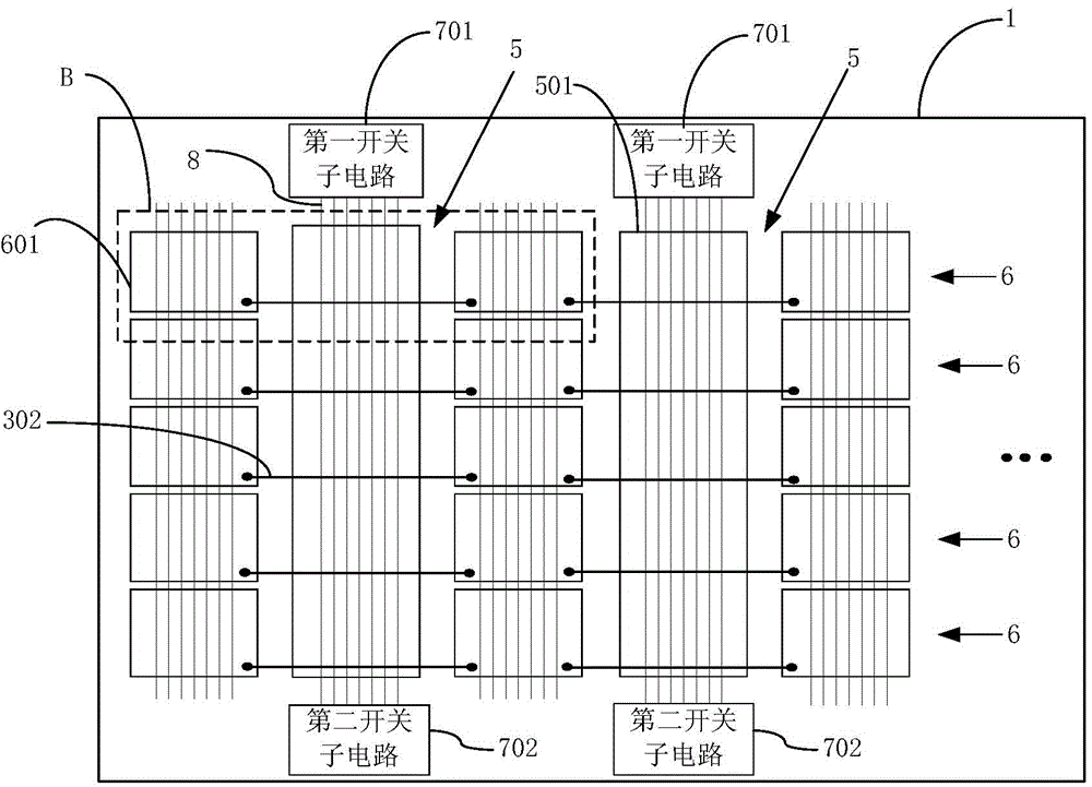
[0044] image 3 It is a schematic structural diagram of the array substrate provided in Embodiment 1 of the present invention, Figure 4 for image 3 The partial enlarged view of the B structure shown, as image 3 and Figure 4 As shown, the array substrate includes: a base substrate 1, on which gate lines, data lines 8, first common electrodes 5 and second common electrodes 6 are formed, the gate lines and data lines 8 define pixel units, Each pixel unit includes a corresponding common electrode base 4, and all the common electrode bases 4 are divided into a plurality of horizontal electrode groups 601 arranged in the row direction and a plurality of vertical electrode groups 501 arranged in the column direction, and the second common electrode 6 includes: a horizontal electrode group 601 on the same row and a metal jumper 302 connecting two adjacent horizontal electrode groups 601 on the same row, and the first common electrode 6 includes: a vertical electrode group 501, ...
Embodiment 2
[0059] Embodiment 2 of the present invention provides a touch screen. The touch screen includes: an array substrate and a color filter substrate. The array substrate and the color filter substrate are arranged oppositely. The described content will not be repeated here.
[0060] The touch screen provided by Embodiment 2 of the present invention includes an array substrate and a color filter substrate. The array substrate includes a base substrate on which gate lines, data lines, first common electrodes, and second common electrodes are formed. A switch circuit is provided between the common electrode and the data line to connect the first common electrode and the data line in parallel during the touch scanning phase. The data lines are connected in parallel, so that the equivalent resistance of the first common electrode is reduced, and the signal-to-noise ratio of the first common electrode is indirectly improved, so that the monitoring of the voltage signal coupled from the ...
Embodiment 3
[0062] Embodiment 3 of the present invention provides a driving method of a touch screen, the driving method includes: in the touch scanning phase, the switch circuit is turned on, so that the first common electrode and the data line are connected in parallel, and the first common electrode or the second common electrode is loaded Touch scanning signal; in the display scanning stage, the switch circuit is disconnected, so that the first common electrode and the data line are disconnected, the display scanning signal scans the gate lines row by row, and the corresponding data line is loaded with the display scanning signal.
[0063] In the driving method of the touch screen provided by Embodiment 3 of the present invention, a switch circuit is provided between the first common electrode and the data line to conduct in the touch scanning phase so that the first common electrode and the data line are connected in parallel. In the control scanning stage, the first common electrode ...
PUM
 Abstract
Description
Claims
Application Information
 - R&D
- Intellectual Property
- Life Sciences
- Materials
- Tech Scout
- Unparalleled Data Quality
- Higher Quality Content
- 60% Fewer Hallucinations
Browse by: Latest US Patents, China's latest patents, Technical Efficacy Thesaurus, Application Domain, Technology Topic, Popular Technical Reports.
© 2025 PatSnap. All rights reserved.Legal|Privacy policy|Modern Slavery Act Transparency Statement|Sitemap|About US| Contact US: help@patsnap.com


