Driving circuit applied to LCD apparatus

a driving circuit and lcd technology, applied in the field of driving circuits applied to lcd apparatuses, can solve the problems of increasing the number of gate driver chips the length of the woa wire needed in the lcd panel, so as to improve the display quality of the lcd panel

Active Publication Date: 2017-04-27
RAYDIUM SEMICON
View PDF1 Cites 2 Cited by
  • Summary
  • Abstract
  • Description
  • Claims
  • Application Information

AI Technical Summary

Benefits of technology

[0032]In an embodiment, resistances of the first COF wire and the second COF wire are far smaller than resistances of the first WOA wire and the second WOA wire and an equivalent resistance between the first output channel of the third driver chip and the signal source is decreased.
[0033]Compared to the prior art, the driving circuit of the LCD apparatus in this invention uses COF wire having lower resistance to replace the coupling of driver chips in series and matches the internal resistance of driver chip with the resistance of WOA wire, so that the difference between the output signal intensities of the last output channel of the previous driver chip and the first output channel of the present driver chip can be largely reduced and the H-band or H-block phenomenon generated in the display frame of LCD panel can be avoided to enhance the display quality of the LCD panel.
[0034]The advantage and spirit of the invention may be understood by the following detailed descriptions together with the appended drawings.

Problems solved by technology

However, with the increasing size and better display quality of the LCD panel, the number of gate driver chips needed in the LCD panel must become larger and the length of WOA wire needed in the LCD panel must become longer.

Method used


Image

  • Driving circuit applied to LCD apparatus
  • Driving circuit applied to LCD apparatus
  • Driving circuit applied to LCD apparatus

Examples


Embodiment Construction

[0042]A preferred embodiment of the invention is a driving circuit applied to a LCD apparatus. In this embodiment, the driving circuit can be a gate driving circuit applied to LCD apparatus and includes a plurality of gate driver chips, but not limited to this.

[0043]At first, a driving circuit including two driver chips applied to the LCD apparatus in the invention is taken as an example.

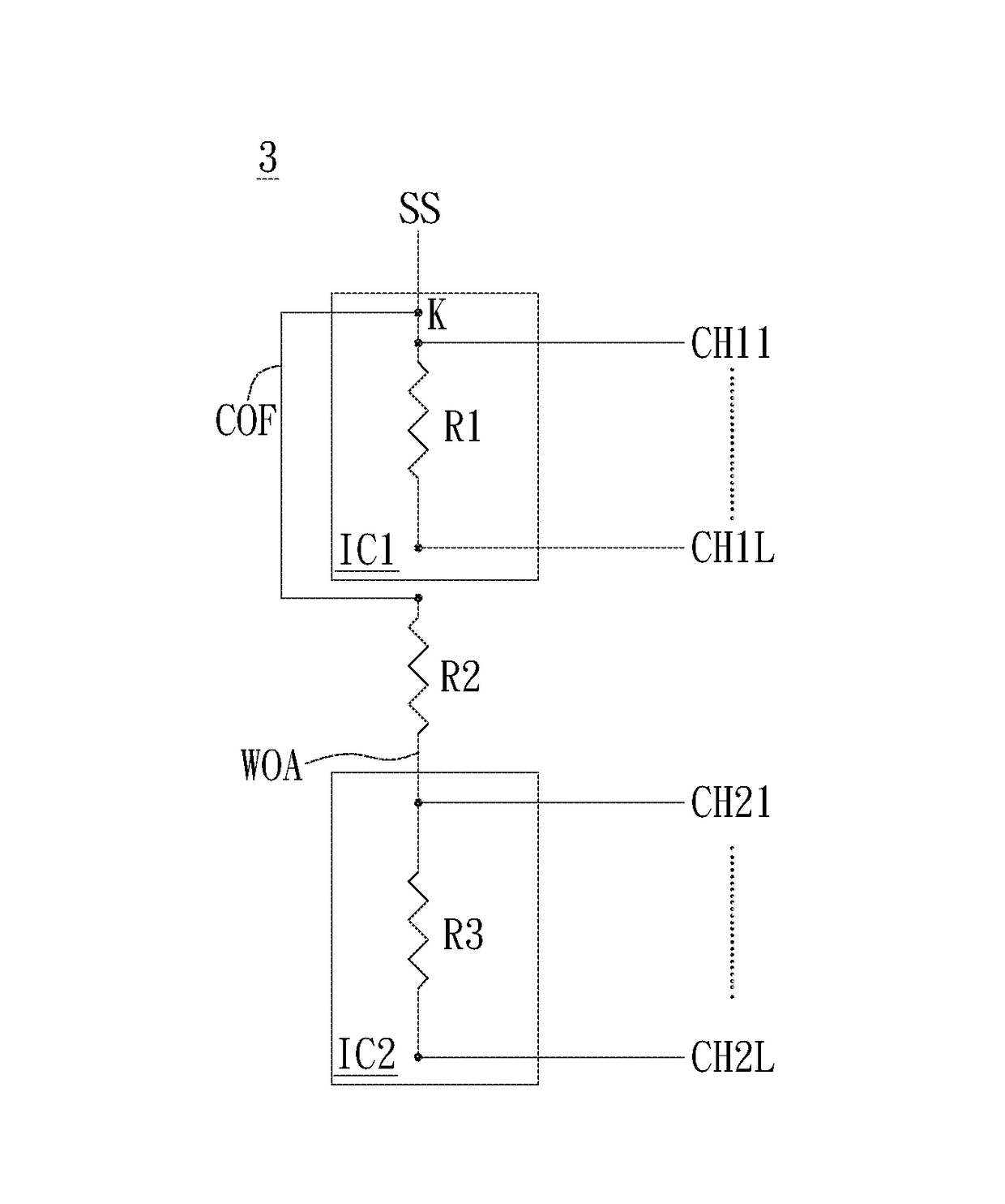
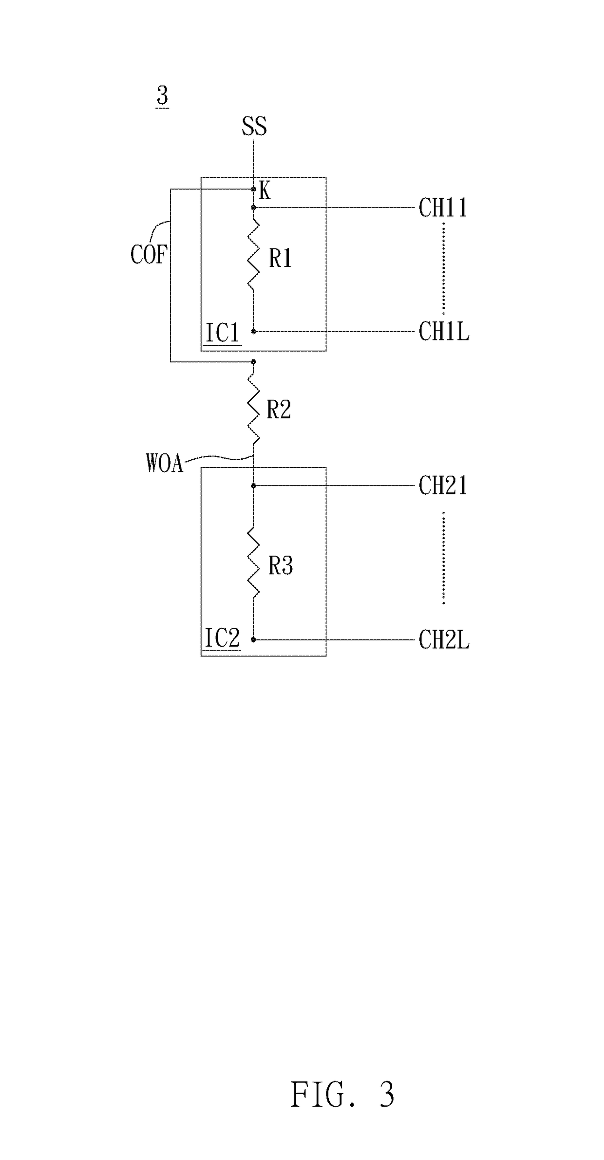
[0044]Please refer to FIG. 3. FIG. 3 illustrates a schematic diagram of the driving circuit 3 applied to the LCD display including the first driver chip IC1 and the second driver chip IC2 in a preferred embodiment of the invention.

[0045]As shown in FIG. 3, the driving circuit 3 includes a signal source SS, a first driver chip IC1, a second driver chip IC2, a wire-on-array wire WOA and a chip-on-film wire COF. Wherein, the first driver chip IC1 and the second driver chip IC2 are both packaged by the COF packaging method. The first driver chip IC1 corresponds and coupled to L output channels CH11˜CH1L...


PUM


Abstract

A driving circuit applied to a LCD apparatus includes N driver chips, a signal source, a WOA wire, a COF wire. Each driver chip is COF-packaged and correspondingly coupled to L output channels. N and L are positive integers and N≧2. The signal source is coupled to L output channels of the first driver chip. One terminal of WOA wire is coupled to L output channels of the second driver chip. One terminal of the COF wire is coupled between the signal source and a first output channel of the first driver chip and another terminal of the COF wire is coupled to another terminal of WOA wire. The resistance of COF wire is far smaller than a first internal resistance between the first output channel and L-th output channel of first driver chip and the resistance of WOA wire is substantially equal to first internal resistance.

Description

BACKGROUND OF THE INVENTION[0001]1. Field of the Invention[0002]This invention relates to a display apparatus, especially to a driving circuit applied to a LCD apparatus.[0003]2. Description of the Prior Art[0004]In general, a liquid crystal display system includes a pixel matrix, two polarizers and a plurality of driver chips. These driver chips are usually packaged by chip on film (COF) technology and coupled to a panel peripheral circuit, so that each row and each column of pixels of the panel can be driven by a driving voltage signal. As shown in FIG. 1, a plurality of gate driver chips IC1˜ICN are coupled in series by the wires disposed on the array substrate WOA, wherein N is a positive integer larger than or equal to 2.[0005]However, with the increasing size and better display quality of the LCD panel, the number of gate driver chips needed in the LCD panel must become larger and the length of WOA wire needed in the LCD panel must become longer.[0006]As shown in FIG. 2, the d...

Claims


Application Information

Patent Timeline
Patent Type & Authority Applications(United States)
IPC IPC(8): G09G3/36
CPCG09G3/3674G09G2320/0204G09G2300/0426G09G2310/0291G09G3/3677G09G2320/0223G09G2320/0233
Inventor HUANG, E-LINGHUANG, CHIH CHUANLIN, WEN-TSUNG
Owner RAYDIUM SEMICON
Why Eureka
Try Eureka