High-effect large-current electromagnetic transmitting system and method

A transmitting system and high-current technology, applied in the field of electromagnetic exploration, can solve the problems of difficult power conversion and transmission efficiency, increase in cost and installation difficulty, and output power consumption, so as to facilitate modular control, improve efficiency, and reduce power consumption. Effect

Active Publication Date: 2015-08-26
OCEAN UNIV OF CHINA
View PDF4 Cites 2 Cited by
  • Summary
  • Abstract
  • Description
  • Claims
  • Application Information

AI Technical Summary

Problems solved by technology

, the power consumption is concentrated on the power semiconductor device, resulting in concentrated heat and difficult heat dissipation
Especially in the case of limited space and heat dissipation conditions of the electromagnetic transmitter cabin under deep sea detection conditions, the design is more difficult, and the cost and installation difficulty are greatly increased
Especially in the occasions where the load resistance is very small and the output current and power are very large, such as the high-power electromagnetic transmitter of the present invention, the load resistance is tens of mΩ, which is close to a short circuit, and the output current is required to reach 1000A. The high internal resistance of the traditional scheme is much greater than load resistance, so most of the output power is consumed on the internal resistance
The circuit principle of the traditional scheme has inherent topology design defects, so it is difficult to achieve high power conversion and transmission efficiency

Method used


Image

  • High-effect large-current electromagnetic transmitting system and method
  • High-effect large-current electromagnetic transmitting system and method
  • High-effect large-current electromagnetic transmitting system and method

Examples


Embodiment 1

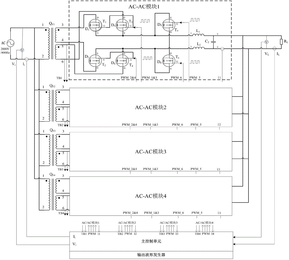
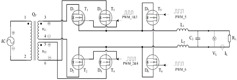
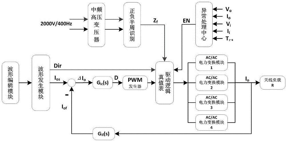
[0026] High-efficiency high-current electromagnetic emission system, including medium-frequency high-voltage power supply, high-current electromagnetic emission module, main control unit and output waveform generator. The high-current electromagnetic emission module is composed of connected high-voltage transformers, power conversion units and current filters; high-voltage transformers The terminal is the input terminal of the high-current electromagnetic transmitting module, which is connected with the intermediate frequency high-voltage power supply, and the current filter terminal is the output terminal of the high-current electromagnetic transmitting module, which is connected with the antenna load.

[0027] The high-voltage transformer is a double-secondary coil transformer with a large conversion ratio, including a primary coil, a secondary coil I and a secondary coil II. The medium-frequency high-voltage power supply adopts a 2000V / 400Hz power supply, and outputs a 60V / 3...

Embodiment 2

[0039] Such as figure 1 As shown, the difference from Embodiment 1 is that there are multiple groups of high-current electromagnetic transmitting modules, and the input terminals of each group are connected in parallel and are all connected to the intermediate frequency high-voltage power supply; the output terminals of each group are connected in parallel and are all connected to the antenna load.

[0040] When multiple high-current electromagnetic emission modules are connected in parallel, the output control module controls the balanced output of each high-current electromagnetic emission module. Such as Image 6 Shown is the system output current waveform diagram when the input current is 120A. In the case of multiple modules connected in parallel, the set current value can also be quickly reached. The current value of each module is basically the same, and the output current is the sum of the current values ​​of each module. When multiple modules are connected in parall...


PUM


Abstract

The invention relates to a high-effect large-current electromagnetic transmitting system, and the system comprises a medium-frequency high-voltage power supply, a large-current electromagnetic transmitting module, a main control unit, and an output waveform generator. The large-current electromagnetic transmitting module consists of a medium-frequency high-voltage transformer, a power conversion unit, and a current filter, wherein the medium-frequency high-voltage transformer, the power conversion unit and the current filter are connected together. The medium-frequency high-voltage transformer employs a large-transformer-ratio double-secondary-coil transformer, and the power conversion unit is located at a secondary coil end of the transformer, comprises two branch circuits and can achieve dipolar output, thereby guaranteeing that the symmetrical operation of the transformer in the positive and negative half cycles. Compared with a conventional transmitter, the system greatly improves the efficiency, and changes the topological structure of a conventional electromagnetic transmitting system. The power conversion unit employs a modularized design, and improves the controllability and expandability of the system.

Description

technical field [0001] The invention belongs to the technical field of electromagnetic exploration, and relates to a high-efficiency and high-current electromagnetic emission system and a control method for realizing high-efficiency and high-power electromagnetic emission by using the system. Background technique [0002] Electromagnetic prospecting theory and technology are currently widely used in petroleum exploration, groundwater exploration, geothermal energy exploration, engineering exploration and site selection, mineral resource exploration, active fault exploration, seismic safety assessment, geological mapping, environmental exploration, dam disease diagnosis, The detection of underground buried objects and pipelines, the definition of seawater intrusion and underground pollution, the monitoring of underground resistivity changes, and the study of crust and upper mantle structures are of great significance, especially in energy exploration. Its theoretical methods ...

Claims


Application Information

Patent Timeline
Patent Type & Authority Applications(China)
IPC IPC(8): G01V3/08
Inventor 黎明刘兰军王建国李予国裴建新刘帅朱仲本杜晓斌
Owner OCEAN UNIV OF CHINA
Why Eureka
Try Eureka