
Current limiting type UPFC system design method

A system design and current limiting technology, applied in flexible AC power transmission systems, emergency protection circuit devices for limiting overcurrent/overvoltage, AC network voltage adjustment, etc., can solve problems that need to be studied

Inactive Publication Date: 2015-05-06
STATE GRID CORP OF CHINA +3
View PDF5 Cites 16 Cited by
  • Summary
  • Abstract
  • Description
  • Claims
  • Application Information

AI Technical Summary

Problems solved by technology

At present, the specific parameter design scheme of the current-limiting UPFC system is still to be studied.

Method used


Image

  • Current limiting type UPFC system design method
  • Current limiting type UPFC system design method
  • Current limiting type UPFC system design method

Examples


Embodiment Construction

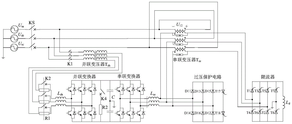
[0032] as attached figure 1 As shown, the normal operation of the current-limiting UPFC system is connected. Both sides of the current-limiting UPFC system are connected to the same AC bus power supply, that is, the voltage levels on both sides of the UPFC are set to be the same, and the phase angle difference is 0°. The parallel side of the UPFC system is connected to the power system through the parallel transformer Tsh, the series side of the UPFC system and the current limiter are connected together through the secondary side of the series transformer Tse, and connected to the power system through the primary side of the series transformer Tse, the series side of the UPFC system and The parallel side is connected through a DC capacitor C, and the filter inductor L on the series side of the UPFC system se A capacitive overvoltage protection circuit is connected in parallel at the exit; the current limiter includes a half-controlled rectifier bridge composed of six thyristor...


PUM


Abstract

The invention discloses a current limiting type UPFC system design method. The two sides of a current limiting type UPFC system are connected to the same alternating-current bus power source, the parallel connection side is connected with a power system through a parallel transformer Tsh, the series connection side of the current limiting type UPFC system and a current limiter are connected together through the secondary side of a series transformer Tse, and connected to the power system through the primary side of the series transformer Tse, the series connection side and the parallel connection side of the UPFC system are connected through a direct-current capacitor C, and an outlet of a series connection side filter inductor of the UPFC system is connected with a capacitor overvoltage protection circuit in parallel. The current limiter comprises a half-controlled rectifier bridge composed of six thyristors, and a follow current bridge composed of two thyristors, wherein the follow current bridge is connected with a current-limiting inductor in parallel; the parallel connection side of the UPFC system is connected with the parallel transformer Tsh through a parallel connection side filter inductor.

Description

technical field [0001] The invention relates to a design method of a current-limiting UPFC system, belonging to the technical field of design of a current-limiting UPFC. Background technique [0002] At present, the research on UPFC (unified power flow controller) limiting short-circuit current is very limited. On the basis of the original UPFC topology, scholars from Zhejiang University proposed a unified power flow controller (referred to as current-limiting UPFC) topology with short-circuit current limiting function. , which consists of a UPFC and a bridge solid-state current limiter connected through a series transformer. During normal operation, the current limiter is equivalent to zero impedance. When a short-circuit fault occurs near the installation point of the device, the current limiter can immediately switch to a high-impedance series connection into the fault circuit to limit the increase rate of the short-circuit current flowing through the device, and at the s...

Claims


Application Information

Patent Timeline
IPC IPC(8): H02J3/16H02H9/02
CPCH02H9/025H02J3/16H02J3/24Y02E40/10Y02E40/30
Inventor 陈晓宇江道灼蔡重凯陈峰李电
Owner STATE GRID CORP OF CHINA
Learn More