
Panoramic image splicing device and method and panoramic image monitoring system

A panoramic image and splicing device technology, applied in the field of panoramic images, can solve the problems of high data transmission capacity, increased power consumption, and affecting system operating speed, etc., to achieve the effect of reducing quantity, reducing power consumption, and speeding up

Active Publication Date: 2015-05-06
GCI SCI & TECH
View PDF5 Cites 14 Cited by
  • Summary
  • Abstract
  • Description
  • Claims
  • Application Information

AI Technical Summary

Problems solved by technology

However, the above-mentioned panoramic video image recording system has the following deficiencies: on the one hand, since the amount of image data transmitted in the multi-angle or panoramic monitoring system is several times that of the single-angle monitoring system, the system requires very high data transmission capabilities; On the other hand, the system also stitches some invalid images, which brings some unnecessary image data to the system, which in turn causes the processor of the system to process a very large amount of data, which affects the operating speed of the system and increased power consumption

Method used


Image

  • Panoramic image splicing device and method and panoramic image monitoring system
  • Panoramic image splicing device and method and panoramic image monitoring system
  • Panoramic image splicing device and method and panoramic image monitoring system

Examples


Embodiment Construction

[0031] The following will clearly and completely describe the technical solutions in the embodiments of the present invention with reference to the accompanying drawings in the embodiments of the present invention. Obviously, the described embodiments are only some, not all, embodiments of the present invention. Based on the embodiments of the present invention, all other embodiments obtained by persons of ordinary skill in the art without making creative efforts belong to the protection scope of the present invention.

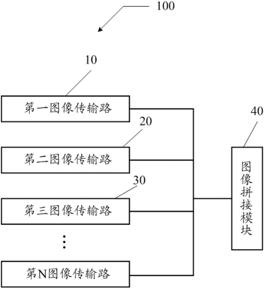
[0032] see figure 1 , figure 1 is a schematic structural diagram of the image stitching device provided by the first embodiment of the present invention. In the embodiment of the present invention, the image stitching device 100 includes at least two image transmission paths and an image stitching module 40, the at least two image transmission paths collect images, and transmit images meeting predetermined requirements to the image stitching module 40. A mod...


PUM


Abstract

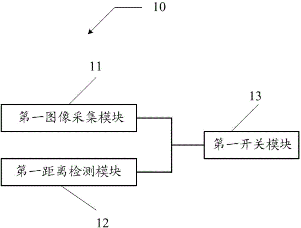
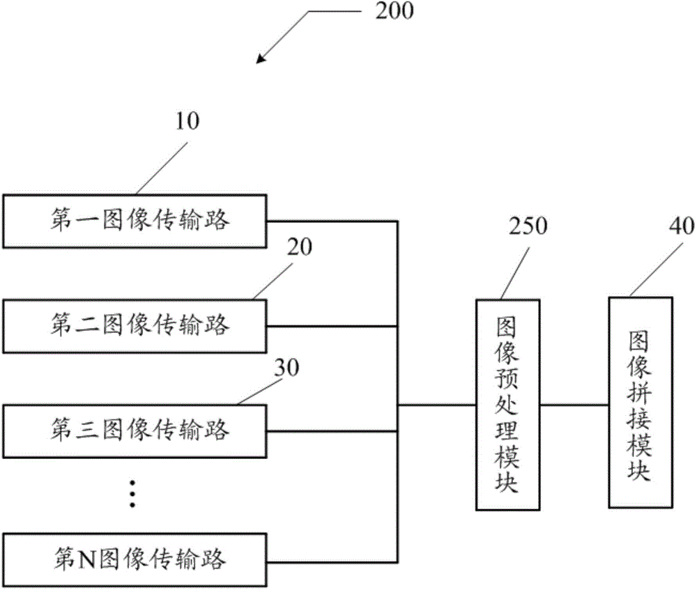
The invention discloses a panoramic image splicing device. The panoramic image splicing device comprises an image splicing module and at least two image transmission paths, wherein each image transmission path comprises an image collection module, a distance detection module and a switch module, and a threshold distance is preset on each distance detection module. When each image collection module images an external object, each distance detection module detects the distance between each image collection module and the external object. When the distance between each image collection module and the external object is larger than or equal to each threshold distance of each distance detection module, each distance detection module controls opening and closing of each switch module, and an image collected by each image collection module is transmitted to the image splicing module through each switch module, and when the distance between each image collection module and the external object is less than each threshold distance of each distance detection module, each distance detection module controls each switch module to disconnect, and the image splicing module splices the image of each switch module and generates a panoramic image. The invention further discloses a panoramic image monitoring system which can accurately perform panoramic monitoring in real time.

Description

technical field [0001] The present invention relates to the field of panoramic images, in particular to a panoramic image splicing device, method and monitoring system. Background technique [0002] Among existing video surveillance systems, video image surveillance systems are widely used in the fields of public security, military detection, private detection, and the like. With the development of technology, the theory, technology and method of panoramic image mosaic are a research hotspot in the field of image processing at present. [0003] Patent CN 103297668A discloses a panoramic video image recording system, which uses multiple cameras to collect images from various directions, and stitches these images into a panoramic image, thereby realizing 360° panoramic monitoring and real-time monitoring. However, the above-mentioned panoramic video image recording system has the following deficiencies: on the one hand, since the amount of image data transmitted in the multi-...

Claims


Application Information

Patent Timeline
Patent Type & Authority Applications(China)
IPC IPC(8): H04N7/18H04N5/265
Inventor 林凡黎天赐黄志华黄建青罗耀荣李盛阳黄剑明成杰宋政杨艳华
Owner GCI SCI & TECH
Learn More