a cystectomy needle
A needle body and gear technology, applied in the field of capsulorhexis, can solve the problems of low success rate of capsulorhexis and difficulty in controlling the size of the capsulorhexis opening, and achieve the effects of simple operation, avoiding intraoperative complications, and improving the success rate
- Summary
- Abstract
- Description
- Claims
- Application Information
AI Technical Summary
Problems solved by technology
Method used
Image
Examples
Embodiment 1
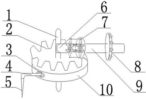
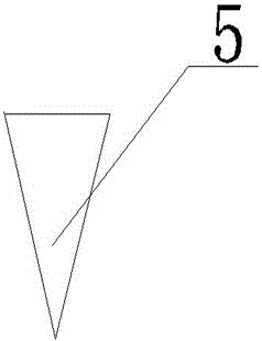
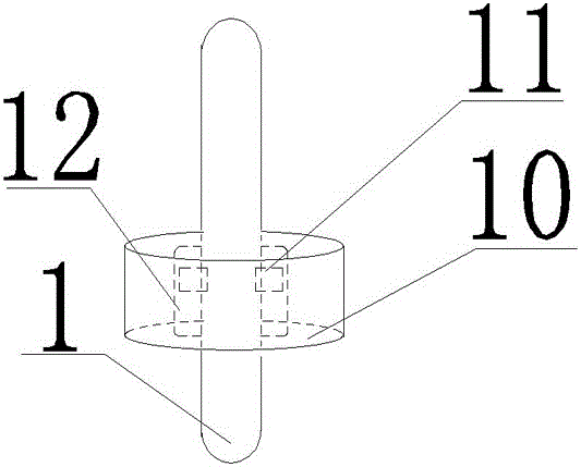
[0032] Such asfigure 1 , figure 2 , image 3 As shown, a cystotomy needle includes a rotating rod 9, a first gear, and a second gear 7 meshing with the first gear. The first gear includes a disc base 10 and gear teeth 2 arranged on the upper surface of the disc base 10. 1. The column 1 that runs through the center of the disc base 10; the upper part of the column 1 is provided with a groove 6, the groove 6 is a cylinder, the rotating rod 9 runs through the center of the second gear 7, and the rotating rod 9 is close to the shape of the end of the second gear 7 Match the shape of the groove 6; the inner surface of the disc base 10 is provided with a slide rail groove 12, the slide rail groove 12 is adapted to the shape of the protruding block 11 arranged on the outer surface of the column 1, and the side end of the disc base 10 is provided with There is a needle body 4, one end of the needle body 4 is installed on the disc base 10 through the fastening structure 3, and the ot...
Embodiment 2
[0035] In this embodiment, on the basis of Embodiment 1, the needle body 4 is perpendicular to the axis of the upright column 1 located at the upper end of the disc base 10, the angle between the needle body 4 and the cutting tip 5 is 90 degrees, and the structure of the needle body 4 is Located on the same side as the column 1 at the lower end of the disc base 10, the specification of the needle body 4 can be determined according to the radius of the capsulorhexis membrane, when the structure of the needle body 4 is perpendicular to the vertical axis of the column 1 structure located at the upper end of the disc base 10 , the radius of the capsulorhexis opening is equal to the distance from the cutting tip 5 at the lower end of the needle body 1 to the center of the column 1, which is equal to the length of the needle body 4 plus the radius of the disc base 10. No longer.
Embodiment 3
[0037] This embodiment is further defined on the basis of the above embodiments, the protruding block 11 is located at the lower end of the groove 6 . Here, the relative positions of the grooves 6 and the protruding blocks 11 that are both arranged on the column 1 are further limited. Preferably, the protruding blocks 11 are located at the lower end of the structure of the grooves 6 . The other structures of this embodiment are the same as those of the foregoing embodiments, and will not be repeated here.
PUM
 Abstract
Description
Claims
Application Information
 - R&D
- Intellectual Property
- Life Sciences
- Materials
- Tech Scout
- Unparalleled Data Quality
- Higher Quality Content
- 60% Fewer Hallucinations
Browse by: Latest US Patents, China's latest patents, Technical Efficacy Thesaurus, Application Domain, Technology Topic, Popular Technical Reports.
© 2025 PatSnap. All rights reserved.Legal|Privacy policy|Modern Slavery Act Transparency Statement|Sitemap|About US| Contact US: help@patsnap.com


