
Robotic Friction Stir Welding System and Its Force-Position Combined Ring Hybrid Control Method

A friction stir and welding system technology, applied in welding equipment, manufacturing tools, non-electric welding equipment, etc., can solve problems such as uneven welding depth, unstable contact force, and affecting welding quality, and achieve consistent welding depth and accurate welding trajectory , Welding uniform effect

Active Publication Date: 2016-09-14
宁波中创焊接技术有限公司
View PDF6 Cites 2 Cited by
  • Summary
  • Abstract
  • Description
  • Claims
  • Application Information

AI Technical Summary

Problems solved by technology

However, the high flexibility of the robot can easily lead to vibration in the friction stir welding process, resulting in a decrease in the motion accuracy of the robot, thereby affecting the welding quality. At the same time, the contact force between the stirring pin and the welded workpiece is not constant during the welding process, resulting in uneven welding depth. uniform

Method used


Image

  • Robotic Friction Stir Welding System and Its Force-Position Combined Ring Hybrid Control Method
  • Robotic Friction Stir Welding System and Its Force-Position Combined Ring Hybrid Control Method
  • Robotic Friction Stir Welding System and Its Force-Position Combined Ring Hybrid Control Method

Examples


Embodiment Construction

[0033] The present invention will be further described below in conjunction with the accompanying drawings.

[0034] The technical solutions in the embodiments of the present invention will be clearly and completely described and discussed below in conjunction with the accompanying drawings of the present invention. Obviously, what is described here is only a part of the examples of the present invention, not all examples. Based on the present invention All other embodiments obtained by persons of ordinary skill in the art without creative efforts belong to the protection scope of the present invention.

[0035] In order to facilitate the understanding of the embodiments of the present invention, specific embodiments are taken as examples for further explanation below in conjunction with the accompanying drawings, and each embodiment does not constitute a limitation to the embodiments of the present invention.

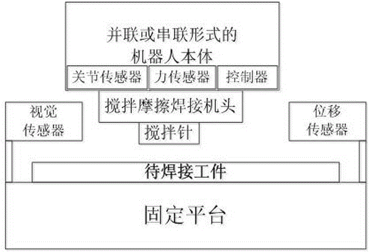
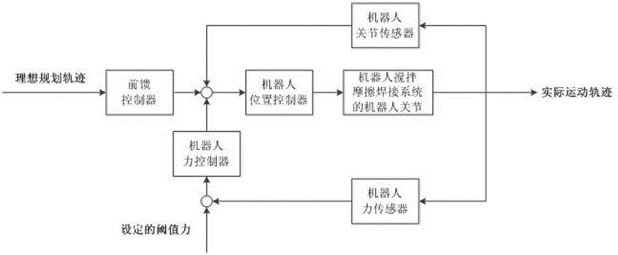
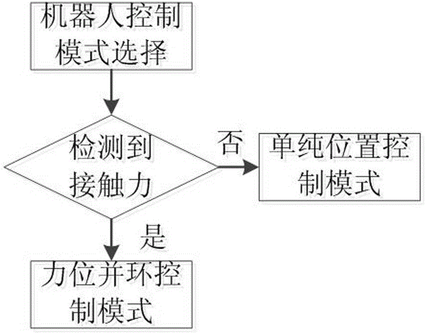
[0036] Such as figure 1 As shown, a robot friction stir welding ...


PUM


Abstract

The invention discloses a robot stirring friction welding system which comprises a robot body, a stirring friction welding machine head, a stirring needle, a fixing platform, a displacement sensor and a visual sensor. The stirring friction welding machine head is arranged below the robot body and fixedly connected with a mechanical arm of the robot body, the robot body controls the stirring friction welding machine head to move, and the stirring needle is arranged below the stirring friction welding machine head and moves along with the stirring friction welding machine head. The displacement sensor and the visual sensor are arranged on the fixing platform, and the fixing platform is used for carrying a workpiece to be welded. The contact force of the stirring needle of the stirring friction welding machine head and the workpiece to be welded is constant, the stirring needle moves along an ideal welding track, welding is uniform, the welding depth is consistent, the welding track is obtained through a control algorithm of an inverse kinematics or kinetic model, the welding track is accurate, convenience and practicability are achieved, and a robot can be controlled in real time to complete the high-precision movement for stirring friction welding.

Description

technical field [0001] The invention relates to a method in the technical field of robot friction stir welding and precision manufacturing, in particular to a robot friction stir welding system and a force-position and loop mixing control method thereof. Background technique [0002] Friction stir welding (FSW) is an innovative advanced friction welding technology. Like conventional friction welding, friction stir welding also uses friction heat and plastic deformation heat as the welding heat source. The high-speed rotation of the head makes it rub against the material of the welding workpiece, so that the temperature of the material at the joint part rises and softens, and the purpose of material welding is completed. The advantage of friction stir welding is that it can realize the connection and manufacture of solid-phase materials. It has the characteristics of high efficiency, low consumption, and low cost. Wide application prospects. The robot has the characteristi...

Claims


Application Information

Patent Timeline
Patent Type & Authority Patents(China)
IPC IPC(8): B23K20/12B23K20/26
CPCB23K20/12B23K20/123B23K20/26
Inventor 谷国迎赵欣郝存蔡智亮许雄沈金华杨洪刚李彦国
Owner 宁波中创焊接技术有限公司
Learn More