
Insert moulding technology die, apparatus, method, and product

A technology of insert molding and mould, which is applied in the direction of coating, etc., can solve the problems of injection molding product approval, control the clamping position of the front mold and the rear mold, and difficult problems, and achieve the effect of improving quality

Inactive Publication Date: 2015-05-13
PERLOSGUANGZHOU ELECTRONICS COMPONENTS +1
View PDF4 Cites 6 Cited by
  • Summary
  • Abstract
  • Description
  • Claims
  • Application Information

AI Technical Summary

Problems solved by technology

During the mold clamping process of the cold runner mold, the front mold and the rear mold are rigidly against each other, so it is difficult to control the clamping position of the front mold and the rear mold at one time through the mold clamping force
In this case, during the mold closing process, it is very easy to cause the mold to be too tight to crush the insert, or the mold to be closed is not in place, which will cause the injection molded product to appear sharp.

Method used


Image

  • Insert moulding technology die, apparatus, method, and product
  • Insert moulding technology die, apparatus, method, and product
  • Insert moulding technology die, apparatus, method, and product

Examples


Embodiment Construction

[0047] The accompanying drawings are given by way of illustration only. The figures are drawn schematically only and not to scale among the various parts. In particular, the spacing therein is shown exaggerated for clarity.

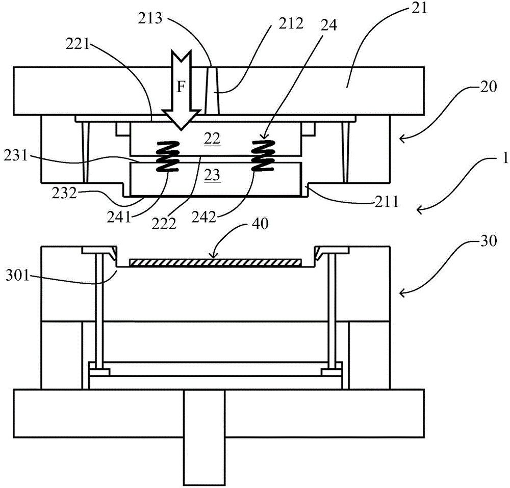
[0048] figure 1 A mold 1 for an insert molding process according to an embodiment of the present invention is shown in an open state.

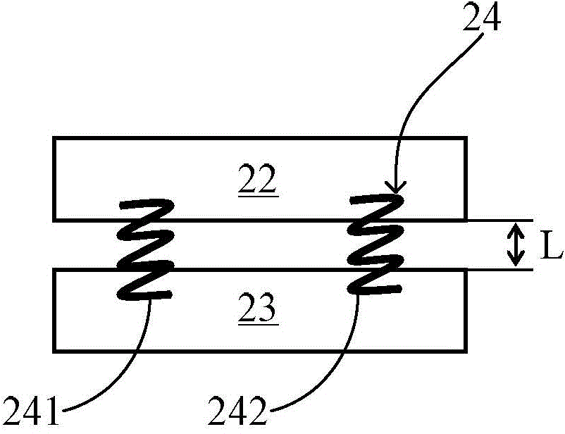
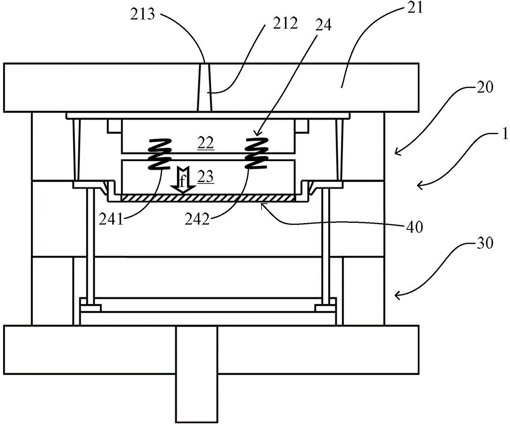
[0049] The mold 1 comprises a first mold part and a second mold part. In this embodiment, the front mold 20 and the rear mold 30 are the front mold 20 and the rear mold 30, respectively. The front mold 20 includes a front mold body 21 , a first movable insert 22 , a second movable insert 23 , and an elastic member 24 connecting the first movable insert 22 and the second movable insert 23 . Both the first movable insert 22 and the second movable insert 23 can translate in a direction toward the mold cavity and in a direction away from the mold cavity. In this embodiment, the elastic member 24 is composed of two compre...


PUM


Abstract

The invention relates a die used for insert moulding technology. The die comprises a first die part and a second die part; the second die part is provided with a core moulding chamber part at a moulding chamber position of the die. The first die part comprises a cavity moulding chamber part, an injection molding inlet, and a runner main body; a first movable mold insert exposed to injection pressure; a second movable mold insert; and an elastic component used for connecting the first movable mold insert and the second movable mold insert; wherein under die assembly states, the moulding chamber of the die are formed by the second movable mold insert, the cavity moulding chamber part, and the core moulding chamber part; the elastic component is configured in a manner that, under die disassembly states, a part of the elastic component is arranged between the first movable mold insert and the second movable mold insert so that the distance between the first movable mold insert and the second movable mold insert is the largest, and under die assembly states, the elastic component is compressed to a largest degree so that the first movable mold insert is pressed against the second movable mold insert. The invention also relates to an apparatus provided with the insert moulding technology die, a method adopting the insert moulding technology die, and a product prepared via the method.

Description

technical field [0001] The present invention relates to a mold for an insert molding process, comprising a first mold part and a second mold part which are separated from each other in a mold-opened state and engaged with each other in a mold-closed state. In particular, the present invention also relates to an apparatus including the mold, an insert molding method using the mold, and a product manufactured using the above insert molding method. Background technique [0002] Insert molding (Insert Molding) process refers to a molding method of an integrated product. [0003] The mold used for the insert molding process mainly consists of two parts, one of which is usually called the front mold, fixed mold or female mold, and the other part is usually called the rear mold, movable mold or male mold. The front mold and the rear mold are separated from each other in a mold-opened state, and engaged with each other in a mold-closed state to form a mold cavity. The front mold i...

Claims


Application Information

Patent Timeline
Patent Type & Authority Applications(China)
IPC IPC(8): B29C45/14B29C45/26
CPCB29C45/0025B29C45/14B29C45/26B29C45/2602B29C2045/0036
Inventor 蒂隆尼·让·塔帕尼利哈瓦伊宁·贾里佩卡·安西奥
Owner PERLOSGUANGZHOU ELECTRONICS COMPONENTS
Learn More