Portable adjustable wall steel bar positioning device

A positioning device and adjustable technology, which is applied in the processing of building materials, construction, building construction, etc., can solve the problems of increasing the cost of construction materials and labor costs, increasing the amount of binding, and affecting the construction progress, so as to reduce construction labor costs And material cost, shorten the construction period, the effect of easy to carry

Pending Publication Date: 2022-05-17
CHINA RAILWAY CONSTR ENG GROUP
View PDF9 Cites 0 Cited by
  • Summary
  • Abstract
  • Description
  • Claims
  • Application Information

AI Technical Summary

Problems solved by technology

From actual use, it can be found that the ladder bars have been bound and fixed inside the steel bars in advance, so they cannot be reused. While increasing the number of workers to bind, it also increases the cost of construction materials and labor costs.
Cement braces are usually fixed on steel bars by means of tying wires. Obviously, cement braces also invisibly increase the amount of binding, which greatly affects the construction progress. In addition, the groove distance of cement braces is much larger than the diameter of steel bars. It is easy to cause the displacement of the main reinforcement and deviate from the target position, the positioning effect is poor, and the role of the cement support is more reflected in the control of the spacing between the horizontal reinforcement, and it is impossible to control and restrict the row spacing of the horizontal reinforcement.

Method used


Image

  • Portable adjustable wall steel bar positioning device
  • Portable adjustable wall steel bar positioning device
  • Portable adjustable wall steel bar positioning device

Examples


Embodiment Construction

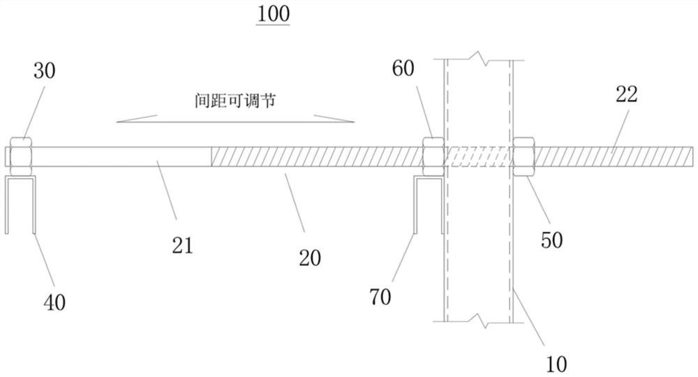
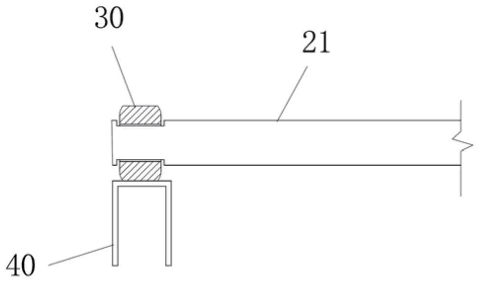
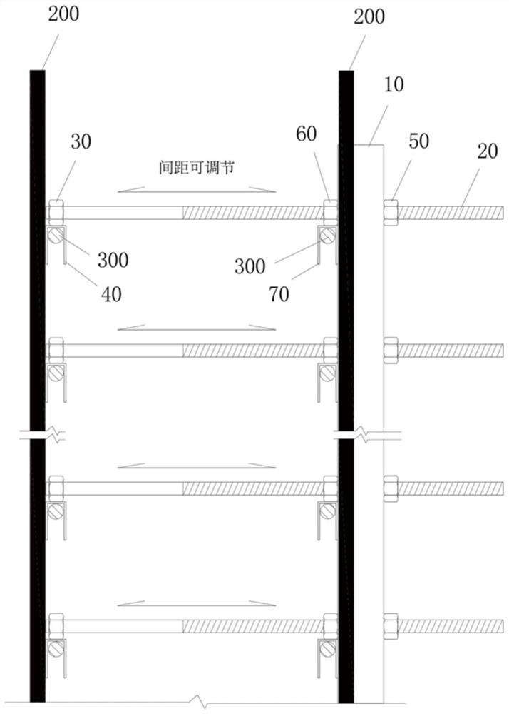
[0014] Such as Figure 1 to Figure 4 As shown, the portable adjustable wall reinforcement positioning device 100 of the present invention includes a vertical tube 10, and the vertical tube 10 is provided with a plurality of positioning bars 20 at intervals from top to bottom. In actual implementation, each positioning bar The rods 20 are arranged on the vertical pipe 10 at equal intervals from top to bottom, and the distance between the two adjacent positioning cross bars 20 up and down is consistent with the row spacing of the horizontal steel bars 300, wherein: the positioning cross bars 20 are divided into smooth sections 21 and There are two parts of the threaded section 22; the end of the smooth section 21 on the positioning cross bar 20 is hinged with an end nut 30, and the end nut 30 is welded with a fixing fixture 40; the threaded section 22 of the positioning cross bar 20 runs through the vertical pipe 10 and is set An adjusting nut 60 and a locking nut 50 are movable...


PUM


Abstract

The invention discloses a portable adjustable wall reinforcing steel bar positioning device which comprises a vertical square pipe, a plurality of positioning cross rods are movably arranged on the vertical square pipe in a penetrating mode from top to bottom at intervals, and each positioning cross rod is divided into a smooth section and a threaded section; an end nut is hinged to the end, located on the smooth section, of the positioning transverse rod and welded to a fixing clamp. The threaded section of the positioning cross rod penetrates through the vertical square tube, an adjusting nut and a locking nut are movably connected to the threaded section in a threaded mode, the adjusting nut and the locking nut are located on the two sides of the vertical square tube respectively, the adjusting nut and the end nut are located on the same side of the vertical square tube, and the adjusting nut is welded to an adjusting clamp. The wall reinforcing steel bar positioning device achieves accurate and rapid positioning of wall reinforcing steel bars, can be used repeatedly, and is suitable for popularization.

Description

technical field [0001] The invention relates to a steel bar positioning device, in particular to a portable and adjustable wall steel bar positioning device. Background technique [0002] In wall construction such as shear walls, the positioning of wall reinforcement is usually achieved using ladder bars or cement braces, etc. The size of the ladder reinforcement needs to be designed according to the thickness of the wall and the thickness of the wall protection layer. Usually, no less than two vertical ladder bars are required for each wall, and horizontal ladder bars are often set on the top of the wall. From actual use, it can be found that the ladder bars have been bound and fixed inside the steel bars in advance, so they cannot be reused. While increasing the number of workers binding, it also invisibly increases the cost of construction materials and labor costs. Cement braces are usually fixed on the steel bars by tying wires. Obviously, the cement braces also invis...

Claims


Application Information

Patent Timeline
Patent Type & Authority Applications(China)
IPC IPC(8): E04G21/18E04G21/12
CPCE04G21/185E04G21/12Y02E10/50
Inventor 宋永涛张悦邢旺韩刚刚刘辉杨新兴祝佳伍李诗阳唐文轩李宇飞
Owner CHINA RAILWAY CONSTR ENG GROUP
Why Eureka
Try Eureka