Oil cup type pad printing machine ink filling structure

A technology of pad printing machine and oil cup, which is applied in the field of ink filling structure of pad printing machine, which can solve the problems of difficult cleaning of ink, uncontrollable ink outflow position of oil cup, air pollution, etc., and achieves easy cleaning or reuse , The effect of cleaning and environmental protection in the treatment process

Active Publication Date: 2015-05-13
长兴艾飞特科技股份有限公司
View PDF10 Cites 3 Cited by
  • Summary
  • Abstract
  • Description
  • Claims
  • Application Information

AI Technical Summary

Problems solved by technology

[0005] In order to solve the problem that when the oil cup is accidentally damaged or overturned during the use of the existing pad printing machine, the outflow position of the ink in the oil cup cannot be controlled, the ink is not easy to clean, and it will cause local serious air pollution. The present invention provides a The accidentally leaked ink is easy to clean up or reuse, and the process is clean and environmentally friendly. The ink filling structure of the ink cup type pad printing machine

Method used


Image

  • Oil cup type pad printing machine ink filling structure
  • Oil cup type pad printing machine ink filling structure

Examples


Embodiment Construction

[0014] The present invention will be further described below in conjunction with the accompanying drawings and specific embodiments.

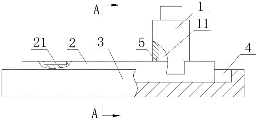
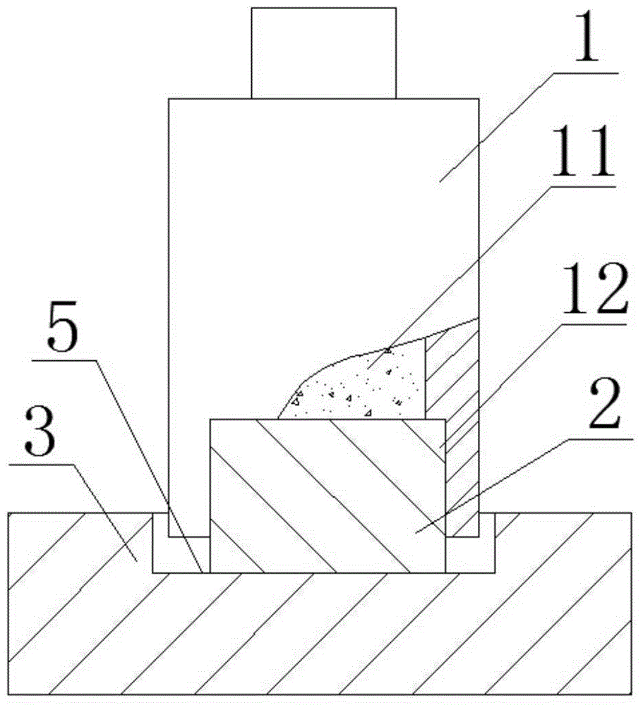
[0015] Such as figure 1 , figure 2 As shown, an oil cup type pad printing machine ink filling structure includes an oil cup 1 with an ink chamber 11 and a pad printing steel plate 2 with a concave pattern 21. There is pad printing ink in the ink chamber 11, and the middle of the lower end of the oil cup 1 There is a rectangular notch 12 that runs through the front and rear walls of the oil cup 1, so that the walls at the lower opening of the oil cup 1 have notches that are penetrated by a rectangular section. The width of the rectangular notch 12 is equal to the width of the pad printing steel plate 2, and the pad printing steel plate 2 fits In the rectangular notch 12 and seal the ink cavity 11, the oil cup 1 slides and fits on the pad printing steel plate 2 at the rectangular notch 12 on it; there is an ink leakage groove 3 under the pad pr...


PUM


Abstract

The invention provides an oil cup type pad printing machine ink filling structure. The purpose is to solve the problems that in the process of using an existing pad printing machine, when an oil cup is accidentally broken or upset, the flowing-out position of ink flowing out from the oil cup can not be controlled, the ink is difficult to clear away, and therefore severe local air pollution will be generated. The oil cup type pad printing machine ink filling structure comprises an oil cup and a pad printing steel plate, wherein the oil cup is provided with an ink cavity, and the pad printing steel plate is provided with a concave pattern. A rectangular notch is formed in the middle of the lower end of the oil cup and is throughout the front and back walls of the oil cup, the width of the rectangular notch is equal to that of the pad printing steel plate, the pad printing steel plate is arranged inside the rectangular notch in a matched mode and seals the ink cavity, and the oil cup is arranged on the pad printing steel plate in a sliding fit mode through the rectangular notch in the oil cup. An ink leaking groove is formed below the pad printing steel plate fixed to the middle of the bottom surface of the inner side of the ink leaking groove, and an ink guiding gap is formed between the outer side face of the pad printing steel plate and the inner wall of the ink leaking groove. A magnet is arranged at the lower end of the oil cup. The oil cup type pad printing machine ink filling structure has the advantages that the ink leaking from the oil cup is guided into the ink leaking groove, in this way, the ink is convenient to clear away or reuse, and the treatment process is clean and environmentally friendly.

Description

technical field [0001] The invention relates to the technical field of ink printing, in particular to an ink filling structure for an oil cup type pad printing machine. Background technique [0002] The working principle of the oil cup pad printing machine is: the oil cup filled with ink moves back and forth in a straight line on the surface of the pad printing steel plate, and the ink in the oil cup fills in the concave pattern on the surface of the pad printing steel plate during the movement; The pad printing rubber head picks up the ink filled in the concave pattern and imprints it on the surface of the printed workpiece to complete the pad printing process. [0003] The existing pad printing machine uses a circular oil cup to do reciprocating linear motion on the flat pad printing steel plate to fill the concave pattern on the surface of the pad printing steel plate with ink. When the cup is accidentally damaged or overturned, the outflow position of the ink in the oil...

Claims


Application Information

Patent Timeline
Patent Type & Authority Applications(China)
IPC IPC(8): B41F17/00B41F31/02
Inventor 杨俊波杨志德
Owner 长兴艾飞特科技股份有限公司
Why Eureka
Try Eureka