Axial flow fan ventilation wall

An axial flow and fan technology, applied in mechanical equipment, non-variable pumps, machines/engines, etc., can solve problems such as inability to achieve airflow effects, shedding, disturbed airflow, etc., and achieve high efficiency and airflow in rated working conditions Stabilizes and prevents vortex shedding

Active Publication Date: 2015-05-13
ZHEJIANG SCI-TECH UNIV
View PDF6 Cites 4 Cited by
  • Summary
  • Abstract
  • Description
  • Claims
  • Application Information

AI Technical Summary

Problems solved by technology

However, since the output air flow of the axial flow fan is a vortex, and according to the fluid characteristics of the wind, two adjacent parallel vortexes will interfere with each other and form vortex shedding, which not only disturbs the normal air flow, but also cannot achieve a single large-scale Air flow effect like axial flow fan

Method used


Image

  • Axial flow fan ventilation wall
  • Axial flow fan ventilation wall

Examples


Embodiment 1

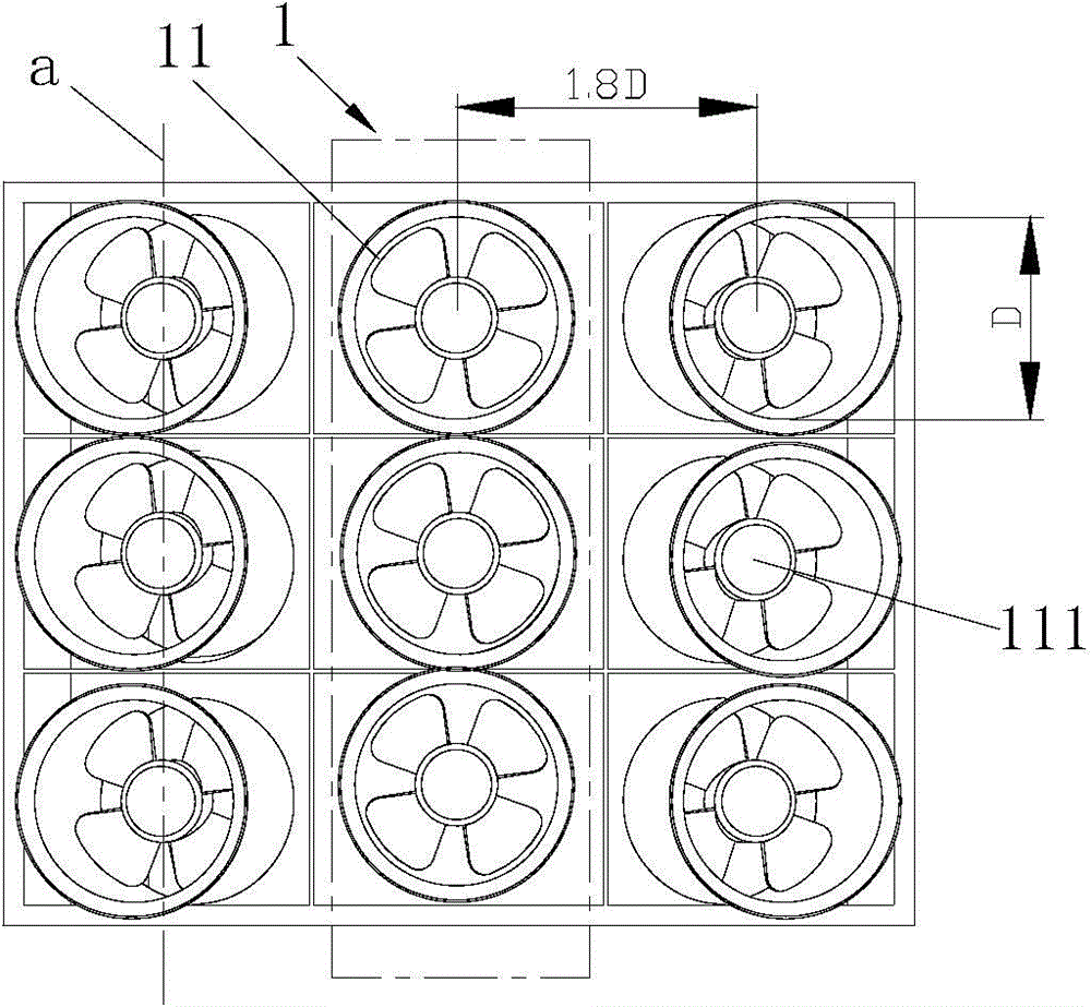
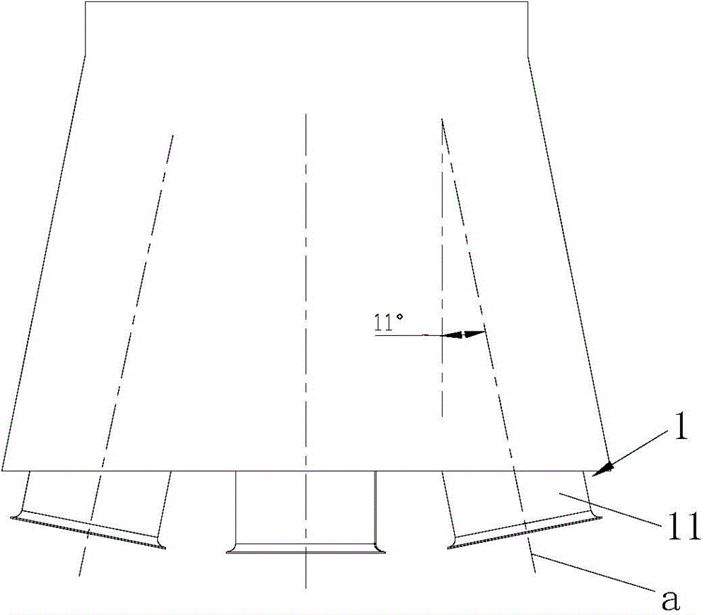
[0018] Embodiment one: if figure 1 , 2 As shown, the present embodiment includes three groups of fan units 1, each group of fan units 1 is composed of three axial flow fans 11 with a diameter of D, and the impeller shafts 111 of the axial flow fans 11 in the same fan group 1 are adjacent to each other. Arranged parallel to each other; the impeller shafts 111 in the same fan unit 1 are located on the same plane, which is named group base plane a; the group base planes a of two adjacent fan units 1 are set at an angle of 11°. In two adjacent fan groups 1, each axial flow fan in one fan group 1 corresponds to each axial flow fan in the other fan group 1 in sequence, and there is a one-to-one correspondence between two adjacent fan groups 1 The center distance of the axial fan 11 is 1.8D. (D is 80cm, the same below)

[0019] Through the CFX fluid dynamics simulation software, the flow rate of this embodiment is 103m 3 / h, when the total pressure is 804Pa, the best rated effici...

Embodiment 2

[0020] Embodiment 2: The only difference from Embodiment 1 is that the base surfaces a of two adjacent fan units 1 are set at an angle of 7°.

[0021] Through the CFX fluid dynamics simulation software, the flow rate of this embodiment is 103m 3 / h, when the total pressure is 823Pa, the best rated efficiency is 86%.

Embodiment 3

[0022] Embodiment 3: The only difference from Embodiment 1 is that the base surfaces a of two adjacent fan units 1 are set at an angle of 13°.

[0023] Through the CFX fluid dynamics simulation software, the flow rate of this embodiment is 103m 3 / h, when the total pressure is 833Pa, the best rated efficiency is 85%.


PUM


Abstract

The invention discloses an axial flow fan ventilation wall which comprises an axial flow fan with the diameter of D. The axial flow fan ventilation wall further comprises two to three fan sets. Each fan set is composed of a plurality of axial flow fans. Impeller shafts of the axial flow fans in the same fan set are adjacent and parallel to one another. All the impeller shafts in the same fan set are located on the same plane which serves as the set cardinal plane. An included angle of 7 degrees to 13 degrees is formed between the set cardinal planes of every two adjacent fan sets, wherein the axial flow fans in one fan set sequentially correspond to the axial flow fans in the other fan set one to one, the central distance between every two corresponding axial flow fans is X, and X is larger than or equal to 1.8D and smaller than or equal to 2.5D. By integrating a plurality of small axial flow fans into a set and making a plurality of sets matched to form a complete ventilation wall, the air flow output by the ventilation wall is just like the air flow output by a single large axial flow fan. The included angle is formed between every two adjacent fan sets, and therefore the air flow interference between the fan sets is effectively avoided, air flow is stable, and the rated working condition efficiency is improved.

Description

technical field [0001] The invention relates to a wind wall, in particular to an axial flow fan wind wall. Background technique [0002] Axial flow fans have a wide range of applications due to their airflow characteristics, and are mainly used in systems such as electric fans, air conditioner external fans, and axial flow wind tunnels. At present, the air flow power is provided by a large axial fan in the axial flow wind tunnel, so as to form a large flow axial air flow in the wind tunnel, in order to meet the needs of corresponding experiments. Axial flow fans are popular for their large air volume and low static pressure, but they also have high energy costs due to their high starting current and low efficiency under rated conditions. [0003] Generally, the power of low-speed wind tunnels is very large, that of medium-sized wind tunnels can reach more than 1,000 kilowatts, and that of large-scale wind tunnels can reach thousands of kilowatts or even tens of thousands of...

Claims


Application Information

Patent Timeline
Patent Type & Authority Applications(China)
IPC IPC(8): F04D25/16
CPCF04D25/166
Inventor 魏义坤陈兴窦华书杨徽陈小平武林李哲弘张滨炜刘琳
Owner ZHEJIANG SCI-TECH UNIV
Why Eureka
Try Eureka