Reflector lamp

A reflective cup and lens technology, which is applied in the field of spotlights, can solve the problems of low light utilization rate, achieve good lighting effect, improve light utilization rate, and improve the effect of optical utilization rate

Inactive Publication Date: 2015-05-20
ETI SOLID STATE LIGHTING ZHUHAI LTD
View PDF6 Cites 6 Cited by
  • Summary
  • Abstract
  • Description
  • Claims
  • Application Information

AI Technical Summary

Problems solved by technology

The existing AR111 spotlight has a light-blocking part on the top, which blocks most of the light on the top of the bulb, and only part of the light is reflected from the top, so the light utilization rate is low

Method used


Image

  • Reflector lamp
  • Reflector lamp
  • Reflector lamp

Examples


Embodiment 1

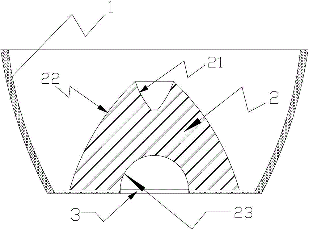
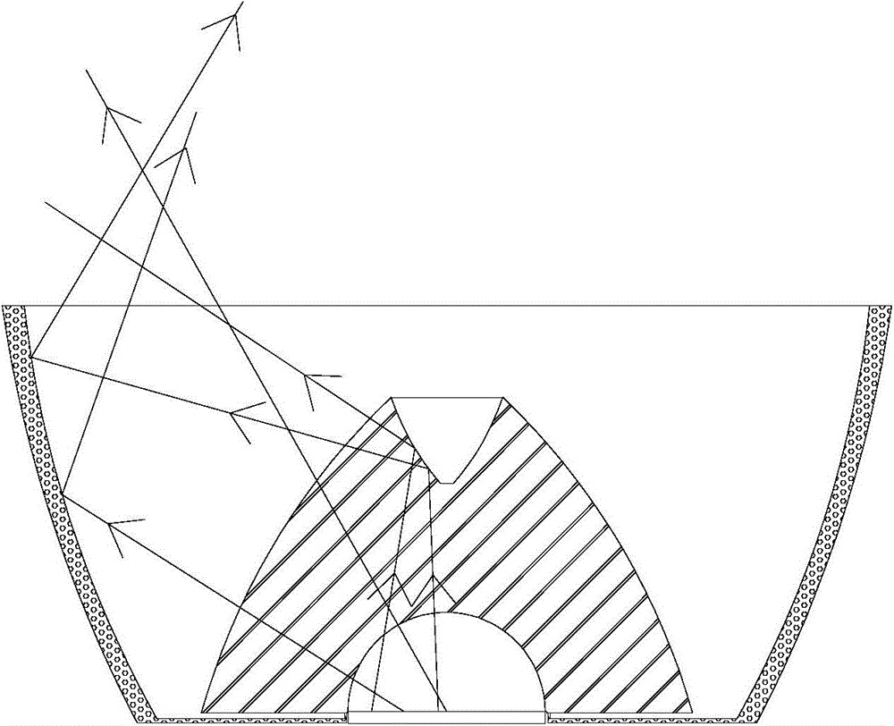
[0031] figure 1 A structural schematic diagram of the combined optical structure of the AR111 spotlight lens and reflector cup in this embodiment is given. The combined optical structure includes a reflective cup, a lens and an LED light source. Wherein, the lens 2 includes three different optically active surfaces: a light-reflecting surface 21 , a light-emitting surface 22 and a light-incoming surface 23 . The light entrance surface 23 is the inner arc surface of a hemisphere or ellipsoid located at the bottom of the lens, the light exit surface 22 is a frustum-shaped outer arc surface located on the outer surface of the lens, and the reflective surface 21 is located on the outer surface of the lens. The inner surface of the inverted truncated cone or cone at the top of the lens, the rotation axes of the light-incoming surface 23, the light-reflecting surface 22 and the light-emitting surface 21 coincide. Such as figure 1 As shown, the lens and the reflective cup are comb...

Embodiment 2

[0035] Such as Figure 4 As shown, the combined optical structure of the lens-reflector cup of this embodiment is different from that of Embodiment 1 in that: the shape of the reflector cup 1 is a concave arc surface rotating cup body. Preferably, the reflector cup 1 emits light corresponding to the spotlight The optical principle of the concave arc rotating cup with an angle greater than or equal to 30 degrees is the same as that of the first embodiment.

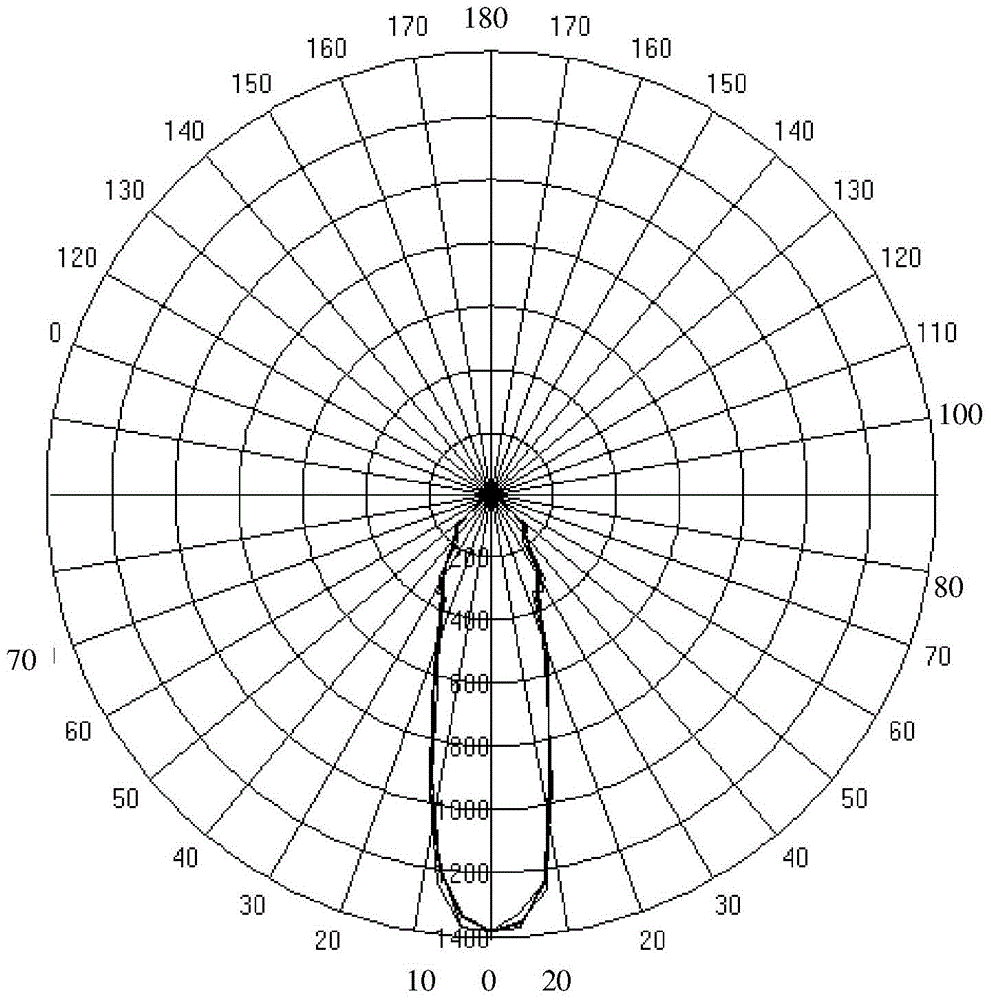
[0036] Figure 5 The light distribution curve of the second implementation is given. Similarly, from the curve, the spotlight of the second embodiment can achieve high-brightness and high-concentration light irradiation within the emission angle of 30 degrees, which can meet the optical effect of the AR111 spotlight lighting, and at the same time The curves indicate high optical utilization.

[0037] from Figure 4 with Figure 5 It can be clearly seen from the light distribution curve of the spotlight that the structur...


PUM


Abstract

The invention provides a reflector lamp. The reflector lamp comprises a reflection cup, a lens and LED light source. An LED light source cavity is formed in the inner end of the lens, and the LED light source is located in the LED light source cavity; a concave reflection cavity is formed in the outer end of the lens, and the wall face of reflection cavity is a reflective face. The lens comprises three different optical acting faces, namely a light inlet face, the reflective face and a light outlet face, a first part of light emitted from the LED light source installed in the LED light source cavity can be projected out from the lens; a second part of the light is emitted to the reflective face, total reflection occurs, the totally reflected light is directly projected out partly, and the remaining part of the totally reflected light is projected out after being reflected by the reflection cup; a third part of the light is emitted to the lens, then projected to the reflection cup and projected out after being reflected. Therefore, by means of the reflector lamp, a good light effect is achieved, and the light use ratio is increased.

Description

technical field [0001] The invention relates to the technical field of lighting equipment, in particular to a spotlight. In particular, it relates to a spotlight with a combined optical structure of lens and reflector cups. Background technique [0002] As a fourth-generation lighting source, LED has significant advantages in energy saving and longevity. With the development of society, the problem of lighting energy consumption in daily life has become increasingly prominent. Therefore, LED lamps with significant energy-saving advantages are more and more popular. Therefore, LED spotlights gradually replace halogen spotlights, among which AR111 is a widely used spotlight. The existing AR111 spotlight has a light-blocking part on the top, which blocks most of the light on the top of the bulb, and only part of the light is reflected from the top, so the light utilization rate is relatively low. Contents of the invention [0003] The technical problem to be solved by the ...

Claims


Application Information

Patent Timeline
Patent Type & Authority Applications(China)
IPC IPC(8): F21S8/00F21V5/04F21V7/10F21V17/00F21Y101/02
CPCF21S8/00F21V5/046F21V7/10F21V17/00F21Y2101/00
Inventor 王冬雷李廷宏夏中明
Owner ETI SOLID STATE LIGHTING ZHUHAI LTD
Why Eureka
Try Eureka