Self-calibration method for measuring system of three-dimensional large-stroke density workbench

A measurement system and workbench technology, which is applied to measurement devices, instruments, and optical devices, etc., can solve the problems of no effective method for 3D workbench calibration, no solution, and lack of workbench self-calibration methods.

Active Publication Date: 2015-05-20
TSINGHUA UNIV +1
View PDF4 Cites 6 Cited by
  • Summary
  • Abstract
  • Description
  • Claims
  • Application Information

AI Technical Summary

Problems solved by technology

However, for the actual 3D workbench, what needs to be calibrated may be a large range of workbench area, or a non-cuboid area such as a cube shape. The current self-calibration method cannot easily obtain the required large-scale area of ​​the 3D workbench. The systematic error G m,n,k , and the existing self-calibration methods do not have an effective method for large-stroke and large-scale three-dimensional workbench calibration, and the original self-calibration technology cannot solve such problems
[0005] According to the above background, the current problems faced by the self-calibration method for the three-dimensional workbench are: the lack of a self-calibration method suitable for large-stroke and large-range workbenches, and the face of large-scale and irregular shapes (such as non-cube shapes) area, there is no proven solution

Method used


Image

  • Self-calibration method for measuring system of three-dimensional large-stroke density workbench
  • Self-calibration method for measuring system of three-dimensional large-stroke density workbench
  • Self-calibration method for measuring system of three-dimensional large-stroke density workbench

Examples


Embodiment Construction

[0038] The technical solution of the present invention will be described in further detail below with reference to the accompanying drawings and specific implementation steps.

[0039] A self-calibration method for a three-dimensional large-stroke precision workbench measurement system disclosed by the present invention is realized through the following technical solutions:

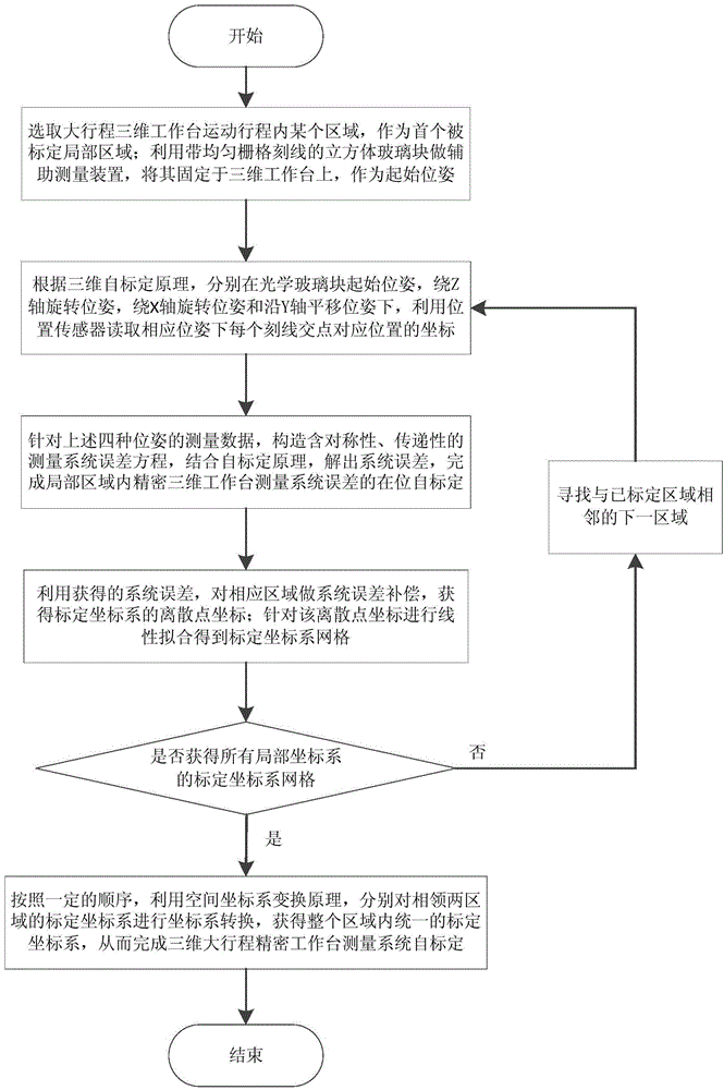
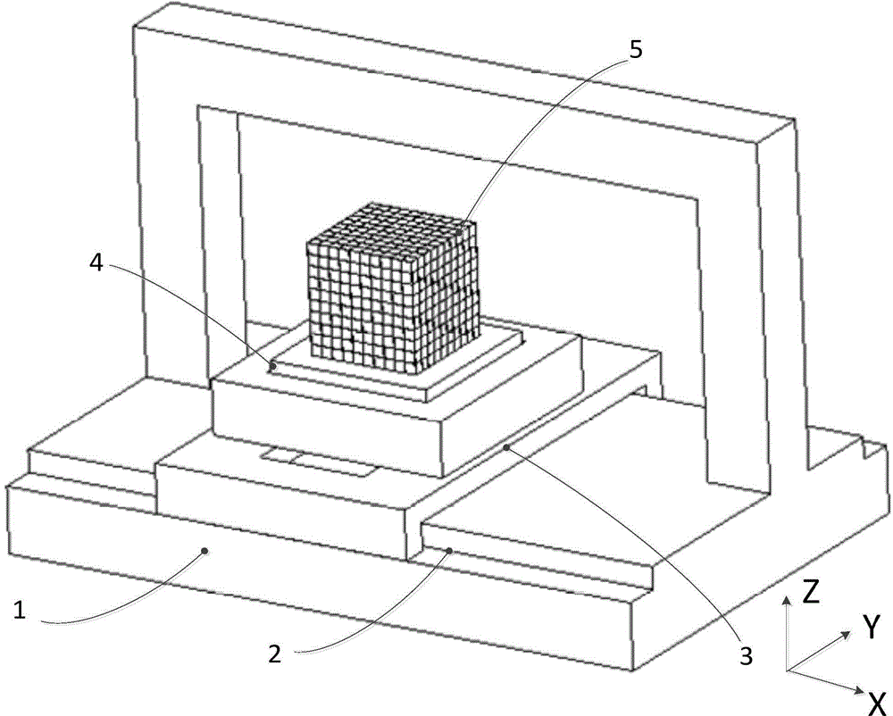
[0040] Please refer to figure 1 , figure 1 It is a flowchart of a self-calibration method for a three-dimensional large-stroke precision workbench measurement system according to the present invention. figure 2 It is a schematic diagram of an experimental system of a self-calibration method for a three-dimensional large-stroke precision workbench measurement system of the present invention. Such as figure 2 As shown, the self-calibration experimental system includes a large-stroke three-dimensional workbench 1 to be calibrated, an X-axis position sensor 2 , a Y-axis position sensor 3 , a Z-axis posit...


PUM


Abstract

The invention discloses a self-calibration method for a measuring system of a three-dimensional large-stroke density workbench, and belongs to the field of precise machining and measurement. The method comprises the following steps: performing self-calibration on the three-dimensional workbench on a regional basis respectively with a three-dimensional self-calibration principle by taking a cubic optical glass block with a uniform grid array as an auxiliary measuring device to obtain the system error of each region; performing system error compensation on corresponding regions; performing linear fitting on the obtained discrete point coordinate of each region; performing coordinate system correction processing on the calibration coordinate systems of adjacent regions in sequence according to a planned sequence to obtain a uniform calibration coordinate system in a whole region, and finishing self-calibration of the three-dimensional large-stroke density workbench measuring system finally. By adopting the method, the large-stroke and high-accuracy self-calibration of the three-dimensional workbench is realized; meanwhile, the function of the high-accuracy three-dimensional workbench is calibrated by using the cubic glass block with the low-precision grid array without any high-accuracy calibration tool, and high calibration accuracy is achieved; the method is suitable for calibrating various three-dimensional precise workbenches.

Description

technical field [0001] The invention relates to a self-calibration method for a three-dimensional large-stroke high-precision workbench measurement system, belonging to the field of ultra-precision processing and measurement. Background technique [0002] The application of ultra-precision worktables in the field of precision engineering is gradually widespread, and the requirements for the measurement accuracy of multi-dimensional workbenches are getting higher and higher. In ultra-precision machining and testing equipment, the requirements for the movement and positioning accuracy of multi-dimensional workbenches are often at the nanometer level. Among them, for the three-dimensional precision workbench with large stroke and large range, limited by the current manufacturing and measurement level, the standard measurement tools required by the traditional workbench calibration method cannot be easily obtained for traditional calibration work, resulting in the ultra-precision...

Claims


Application Information

Patent Timeline
Patent Type & Authority Applications(China)
IPC IPC(8): G01B11/00
Inventor 胡楚雄朱煜徐振源杨进张鸣杨开明徐登峰穆海华尹文生胡金春成荣
Owner TSINGHUA UNIV
Why Eureka
Try Eureka