Electronic instrument and electronic instrument manufacturing method and device

A kind of electronic equipment and plating technology, applied in the direction of telephone structure, electrical digital data processing, data processing input/output process, etc., can solve the problem that the visual effect of the screen window area and the ink area cannot be consistent, etc.

Active Publication Date: 2015-05-20
HUAWEI DEVICE CO LTD
View PDF7 Cites 8 Cited by
  • Summary
  • Abstract
  • Description
  • Claims
  • Application Information

AI Technical Summary

Problems solved by technology

[0007] Embodiments of the present invention provide an electronic device, a manufacturing method and a device for the electronic device, which are used to solve the technical problem in the prior art that the visual effects of the screen window area and the ink area of ​​the electronic device cannot be consistent

Method used


Image

  • Electronic instrument and electronic instrument manufacturing method and device
  • Electronic instrument and electronic instrument manufacturing method and device
  • Electronic instrument and electronic instrument manufacturing method and device

Examples


example 1

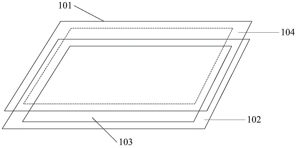
[0055] For example, the refractive index matching layer 104 uses high refractive index film material Nb2O5 (refractive index at 550nm wavelength is 2.3) and low refractive index film material Al2O3 (refractive index at 550nm wavelength is 1.63), which is based on the high and low refractive index The choice is based on the principle that the difference between the film layers is relatively large and it is easy to achieve refractive index matching.

[0056] The refractive index matching layer 104 is realized by having a symmetrical film layer structure, and the increase in the number of film layers will reduce the adhesion of the film, so the symmetrical film system Al2O3 / Nb2O5 / Al2O3 film layer structure with the least number of film layers is used, that is, N=3 , there are three refractive index matching layers 104, wherein the material of the first refractive index matching layer 104 is Al2O3, the material of the second refractive index matching layer 104 is Nb2O5, and the mat...

example 2

[0059] The refractive index matching layer 104 is made of high refractive index film material CeO2 (refractive index at 550nm wavelength is 2.20) and low refractive index film material Al2O3 (refractive index at 550nm wavelength is 1.63), which is based on the high and low refractive index film layer The larger the difference, the easier it is to realize the principle of refractive index matching.

[0060] The refractive index matching layer 104 is realized by having a symmetrical film layer structure, and the increase in the number of film layers will reduce the adhesion of the film, so the symmetrical film system Al2O3 / CeO2 / Al2O3 film layer structure with the least number of film layers is used, that is, N=3 , there are three refractive index matching layers 104, wherein the material of the first refractive index matching layer 104 is Al2O3, the material of the second refractive index matching layer 104 is CeO2, and the material of the third refractive index matching layer 10...

example 3

[0070] For example, the refractive index matching layer 104 uses high refractive index film material Nb2O5 (refractive index at 550nm wavelength is 2.3) and low refractive index film material Al2O3 (refractive index at 550nm wavelength is 1.63), which is based on the high and low refractive index The choice is based on the principle that the difference between the film layers is relatively large and it is easy to achieve refractive index matching.

[0071] The refractive index matching layer 104 is realized by having a symmetrical film layer structure, and the increase in the number of film layers will reduce the adhesion of the film, so the symmetrical film system Al2O3 / Nb2O5 / Al2O3 film layer structure with the least number of film layers is used, that is, N=3 , there are three refractive index matching layers 104, wherein the material of the first refractive index matching layer 104 is Al2O3, the material of the second refractive index matching layer 104 is Nb2O5, and the mat...


PUM


Abstract

An electronic device is used for making a screen window area of the electronic device consistent with a visual effect of an ink area. The electronic device comprises: a cover plate, an ink layer and a touch display layer located under the cover plate, and N layers of refractive index matching layers plated between the cover plate and the ink layer, wherein N is a positive integer and the refractive index matching layers are used for making a difference between a reflectivity of the ink layer and a reflectivity of the touch display layer smaller than a preset threshold. Also disclosed are a method and an apparatus for manufacturing the electronic device.

Description

technical field [0001] The invention relates to the field of mechanical manufacturing, in particular to an electronic device, a manufacturing method and a device for the electronic device. Background technique [0002] The shape of a mobile phone is the first element to attract consumers' attention. It can arouse consumers' psychological desire to buy, and it is also the external expression of the internal functions, configuration and quality of mobile phones. With the popularization of mobile phones, the differentiation of consumers is becoming more and more obvious, and the multi-level demand is getting stronger and stronger. With the increasing aesthetic level of consumers, the requirements for the appearance design of mobile phones are also getting higher and higher. [0003] In the mobile phone, the reflected light of the ink area (BM) mainly comes from the reflected light of the upper surface of the cover (Cover Lens) and the reflected light of the ink on the lower su...

Claims


Application Information

Patent Timeline
Patent Type & Authority Applications(China)
IPC IPC(8): G06F3/041H04M1/02
CPCG06F3/0412G06F1/1637G06F1/1643G06F2203/04103
Inventor 姜鹏李伟林耿邓常猛王河
Owner HUAWEI DEVICE CO LTD
Why Eureka
Try Eureka