
Display driving device of automated instrument

A display driver and instrument technology, applied in instruments, static indicators, etc., can solve the problems of high cost of use and large space occupied, and achieve the effect of simple wiring, solving the problems of cost and space occupation, and convenient and effective use.

Inactive Publication Date: 2015-05-20
CHENGDU ZHONGYUANXIN ELECTRONICS TECH
View PDF0 Cites 0 Cited by
  • Summary
  • Abstract
  • Description
  • Claims
  • Application Information

AI Technical Summary

Problems solved by technology

[0002] The current automatic instrument display uses an organic EL display, which is also used in the display of mobile phones and watches. The flyback converter used in the traditional EL drive device is too expensive to use and takes up too much space.

Method used


Image

  • Display driving device of automated instrument

Examples


Embodiment Construction

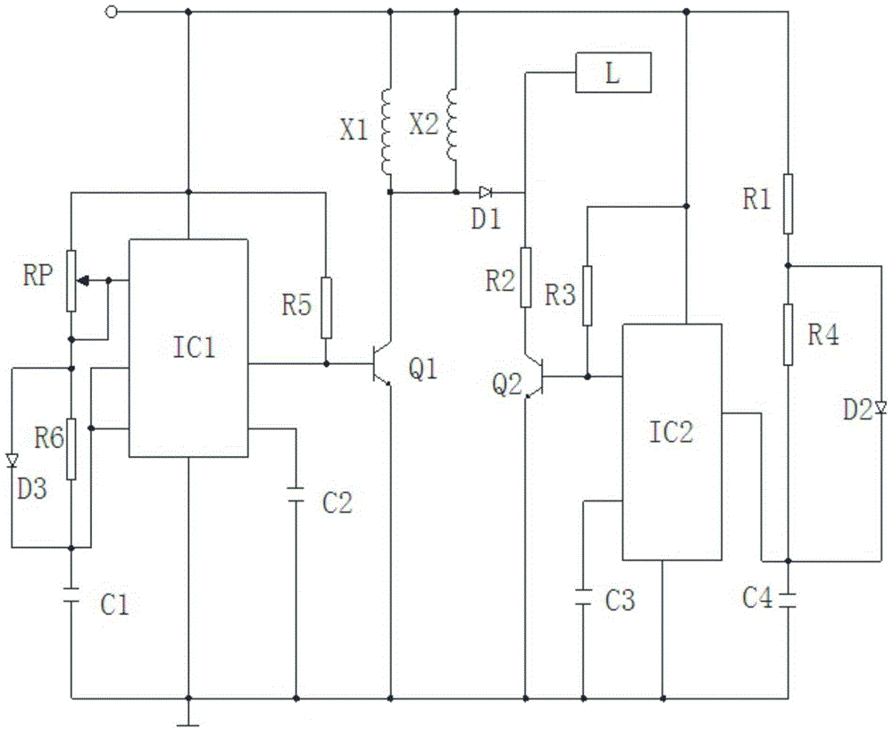
[0009] The present invention will be further described below in conjunction with accompanying drawing:

[0010] Such as figure 1 As shown, the present invention includes a first inductor X1, a second inductor X2, a display L, a first resistor R1, a second resistor R2, a third resistor R3, a fourth resistor R4, a fifth resistor R5, a sixth resistor R6, a potential Device RP, first capacitor C1, second capacitor C2, third capacitor C3, fourth capacitor C4, first transistor Q1, second transistor Q2, first diode D1, second diode D2 , the third diode D3, the first integrated chip IC1 and the second integrated chip IC2. One end, the power input end of the second integrated chip IC2, the first end of the first resistor R1, the first end of the fifth resistor R5, the power input end of the first integrated chip IC1 and the first end of the potentiometer RP are connected, The second end of the first resistor R1 is simultaneously connected to the first end of the fourth resistor R4 an...


PUM


Abstract

The invention discloses a display driving device of an automated instrument. The display driving device comprises a first inductor, a second inductor, a display, a first resistor, a second resistor, a third resistor, a fourth resistor, a fifth resistor, a sixth resistor, a potentiometer, a first capacitor, a second capacitor, a third capacitor, a fourth capacitor, a first triode, a second triode, a first diode, a second diode, a third diode, a first integrated chip and a second integrated chip. The display driving device is simple in circuit and convenient and effective in use; different from a conventional EL driving circuit, an EL display driving circuit composed of the integrated chips is composed of low-loss NE555 integrated chips and several switch transistors, so that the problems of cost generated by and space occupied by a regression converter which is adopted in the conventional EL driving circuit are solved.

Description

technical field [0001] The invention relates to a display driving device, in particular to a display driving device of an automatic instrument. Background technique [0002] The current automation instrument displays use organic EL displays, which are also used in the displays of mobile phones and watches. The flyback converters used in traditional EL drive devices are too expensive to use and occupy too much space. Contents of the invention [0003] The object of the present invention is to provide a display driving device for an automatic instrument in order to solve the above problems. [0004] The present invention achieves the above object through the following technical solutions: [0005] The present invention includes a first inductor, a second inductor, a display, a first resistor, a second resistor, a third resistor, a fourth resistor, a fifth resistor, a sixth resistor, a potentiometer, a first capacitor, a second capacitor, a third resistor Capacitor, fourth ...

Claims


Application Information

Patent Timeline
IPC IPC(8): G09G3/32G09G3/3208
Inventor 龙宁
Owner CHENGDU ZHONGYUANXIN ELECTRONICS TECH
Learn More