Overcurrent protection circuit of push-pull converter

A technology of overcurrent protection circuit and push-pull circuit, which is applied in the direction of emergency protection circuit devices and electrical components, and can solve the problem of increasing the asymmetry of the two windings on the input side of the push-pull converter, adding lines and components, transformer bias, etc. problems, to achieve the effect of reducing line asymmetry, reducing possibility, and simplifying lines

Active Publication Date: 2013-01-09
EAST GRP CO LTD
View PDF7 Cites 6 Cited by
  • Summary
  • Abstract
  • Description
  • Claims
  • Application Information

AI Technical Summary

Problems solved by technology

At present, in some uninterruptible power supply products, a current transformer is added to the input side to sample the input side current and send it to the comparison circuit to generate a protection signal to the controller, and the controller turns off the drive of the push-pul

Method used


Image

  • Overcurrent protection circuit of push-pull converter
  • Overcurrent protection circuit of push-pull converter
  • Overcurrent protection circuit of push-pull converter

Examples


Embodiment Construction

[0017] The present invention will be further described with reference to the following examples.

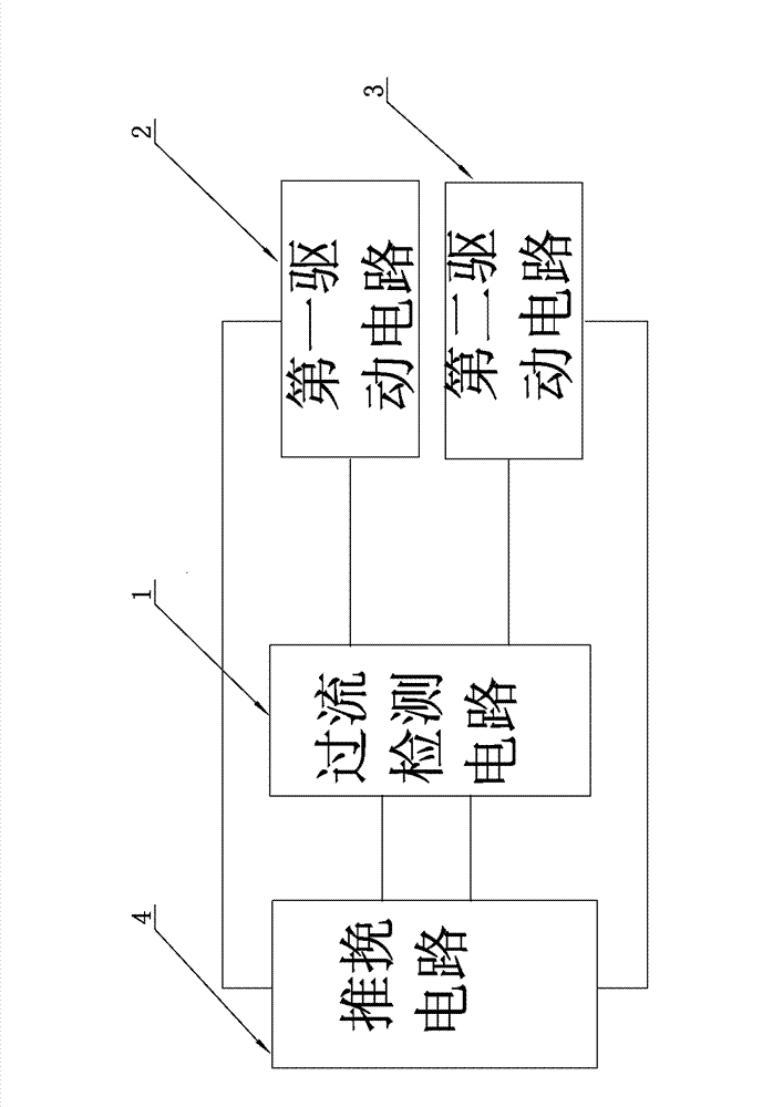
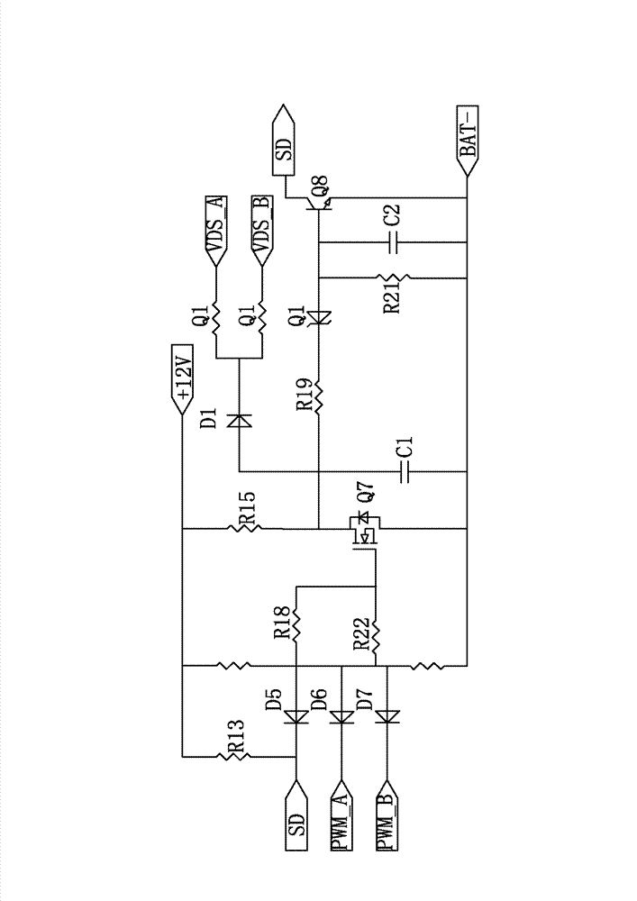
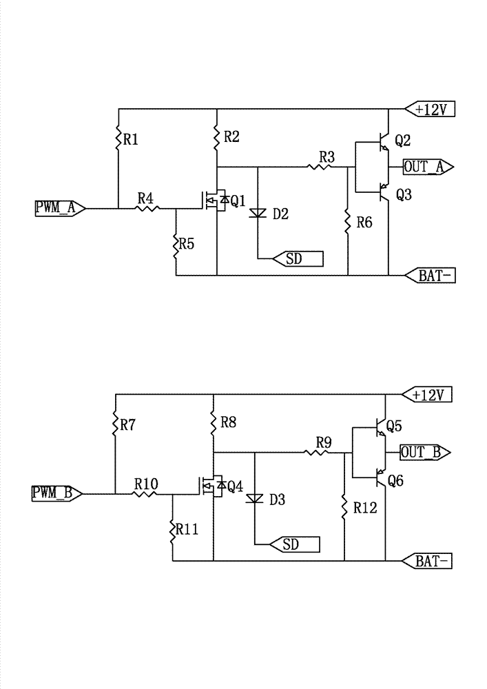
[0018] A specific implementation of a push-pull converter overcurrent protection circuit of the present invention, such as Figures 1 to 4 As shown, it includes: a push-pull circuit 4, a first drive circuit 2 and a second drive circuit 3 for generating drive signals for the switch tubes of the push-pull circuit 4, and an overcurrent detection circuit 1, the overcurrent detection circuit 1. When the voltage signal at both ends of the switch tube output of the push-pull circuit 4 is measured to be over-voltage, the corresponding drive circuit is blocked.

[0019] During the circuit operation, the overcurrent detection circuit 1 obtains the voltage signal at both ends of the switch tube in the push-pull converter, and generates a valid / invalid overcurrent protection signal SD according to the voltage signal; and the overcurrent protection signal SD is valid when The first driving c...


PUM


Abstract

The invention relates to the technical field of a push-pull converter, in particular to an overcurrent protection circuit of the push-pull converter. The overcurrent protection circuit structurally comprises a push-pull circuit, a first driving circuit, a second driving circuit and an overcurrent detection circuit, wherein the first driving circuit and the second driving circuit are used for generating driving signals of a switch tube of the push-pull circuit, and the overcurrent detection circuit closes corresponding driving circuits when detecting that voltage signals at two output ends of the switch tube of the push-pull circuit are in overvoltage. Compared with the prior art, sampling of incoming current is not needed, namely a current transformer is not needed, lines of the converter are simplified, use of elements is reduced, possibility that two winding lines on input sides of the push-pull converter are asymmetrical is reduced, and a transformer is not easy to bias.

Description

technical field [0001] The invention relates to the technical field of push-pull converters, in particular to a push-pull converter overcurrent protection circuit. Background technique [0002] At present, in the power segment below 3KVA of the uninterruptible power supply, a push-pull converter is usually used to perform DC conversion from the battery to the DC bus. The push-pull converter has high requirements on the symmetry of the upper and lower bridges on the input side. If the difference between the windings on the input side of the transformer of the push-pull converter is too large, or the trace length difference between the upper and lower bridges on the circuit board is too large, or the upper and lower bridges are too different. There is a certain deviation in the driving pulse width of the bridge switch tube, which will cause the transformer to produce a bias phenomenon. When the bias magnetism gradually accumulates, the input current of the bias magnet winding...

Claims


Application Information

Patent Timeline
IPC IPC(8): H02H7/12
Inventor 方晓云
Owner EAST GRP CO LTD
Why Eureka
Try Eureka