
Ground wire noise eliminating circuit

A technology of noise elimination and ground wire, which is applied in the field of ground wire noise isolation unit, can solve the problems of sound quality impact, large volume of audio transformer, high cost, etc., and achieve the effect of being conducive to production, simple circuit and low cost

Active Publication Date: 2012-09-12
AUTOLINK ELECTRONICS
View PDF3 Cites 6 Cited by
  • Summary
  • Abstract
  • Description
  • Claims
  • Application Information

AI Technical Summary

Problems solved by technology

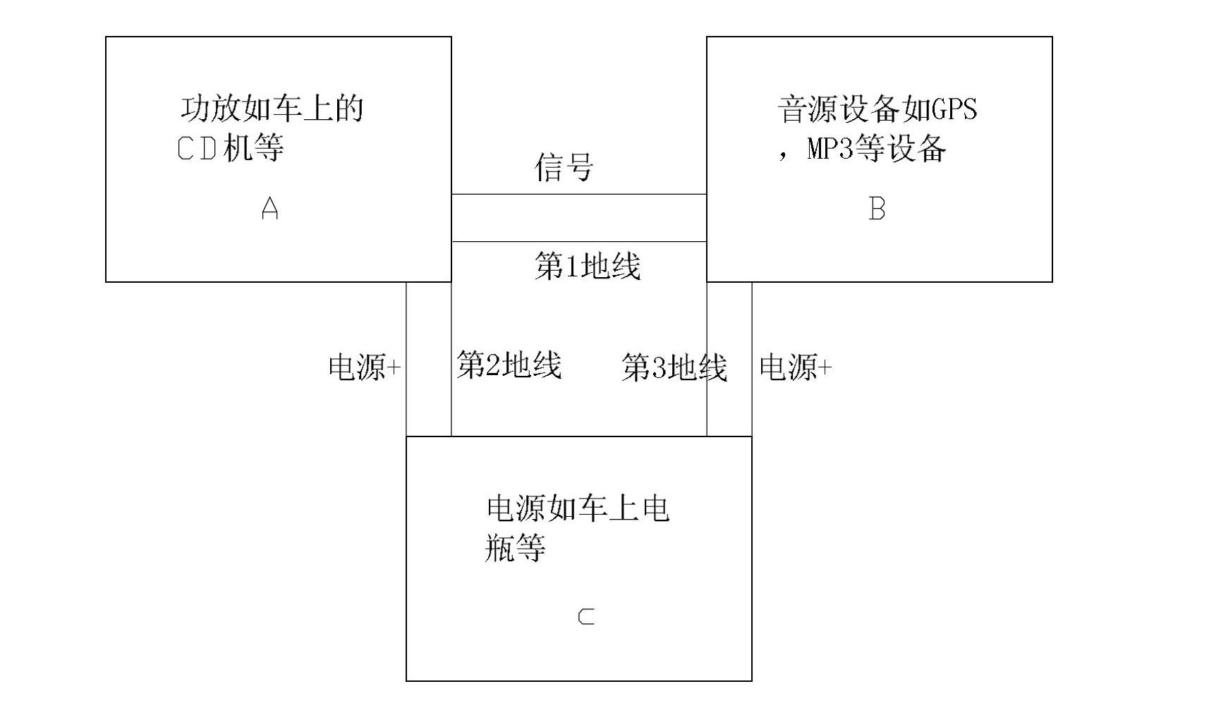
Due to ground noise U G It cannot be added to the input of power amplifier A, so this method is very useful, but because the frequency response of the audio transformer is generally poor, it will seriously affect the sound quality, and the audio transformer is large in size and high in cost

Method used


Image

  • Ground wire noise eliminating circuit
  • Ground wire noise eliminating circuit
  • Ground wire noise eliminating circuit

Examples


Embodiment Construction

[0032] First, the root cause of ground noise is explained based on signal analysis:

[0033] Specific circuit analysis such as Figure 5 shown, the ground noise U G It will divide the voltage to the signal input terminal of the power amplifier A through the output equivalent resistance RO and the input equivalent resistance RI. Usually, RI is much larger than RO. Therefore, the ground noise U G It is equivalent to fully adding to the input of the power amplifier A, that is to say, a ground noise U is superimposed on the signal. G ’, this ground noise U G ’ Even though it’s small, it becomes very large when it passes through the amplifier A.

[0034] Second, explain the core of the present invention according to the source of the ground wire noise:

[0035] Such as Figure 6 , the ground wire noise elimination circuit of the present invention adds a differential amplifier U3-A between the power amplifier A and the independent sound source device B, and the ground wire nois...


PUM


Abstract

The invention relates to a ground wire noise eliminating circuit, which is connected between a power amplifier (A) and independent sound source equipment (B), and is characterized by comprising a differential amplifier (U3-A) of which the output end is electrically connected with the audio signal input of the power amplifier and the input end is connected with the audio output of independent sound source equipment and independent sound source equipment ground (B-GND) respectively, wherein power amplifier ground (A-GND) is electrically connected with differential amplifier ground; and the power amplifier ground is electrically connected with the independent sound source equipment ground through common power supply (C) ground. The circuit has the advantages of good ground wire noise suppressing effect, high audio index, simple circuit, low cost, small size and contribution to production.

Description

technical field [0001] The invention relates to an electronic circuit, in particular to a ground line noise elimination circuit, in particular to a ground line noise isolation unit in a vehicle audio circuit. Background technique [0002] Such as Figure 1-3 , the car audio circuit includes power amplifier A, independent audio device B, and the DC power supply C shared by power amplifier A and independent audio device B, and the ground wire of the three is shared. In practical applications, the current flowing through power amplifier A and independent audio device B There is a certain amount of AC components. Since the ground wire resistance between the power amplifier A, the independent audio source device B and the DC power supply C cannot be zero, an AC voltage will be generated between the three, and the power amplifier A and the independent audio source device B The AC voltage between is what we usually call the ground noise U G , this noise will be amplified by power ...

Claims


Application Information

Patent Timeline
IPC IPC(8): H04R3/02
Inventor 朱志文
Owner AUTOLINK ELECTRONICS
Learn More