

High-threshold value voltage comparison circuit consisting of high-precision low-voltage comparator
A high-threshold voltage, comparison circuit technology, applied in multiple input and output pulse circuits and other directions, to achieve the effect of simple circuit, expanded use range, and low power consumption
- Summary
- Abstract
- Description
- Claims
- Application Information
AI Technical Summary
Problems solved by technology
Method used
Image

Examples
Embodiment Construction
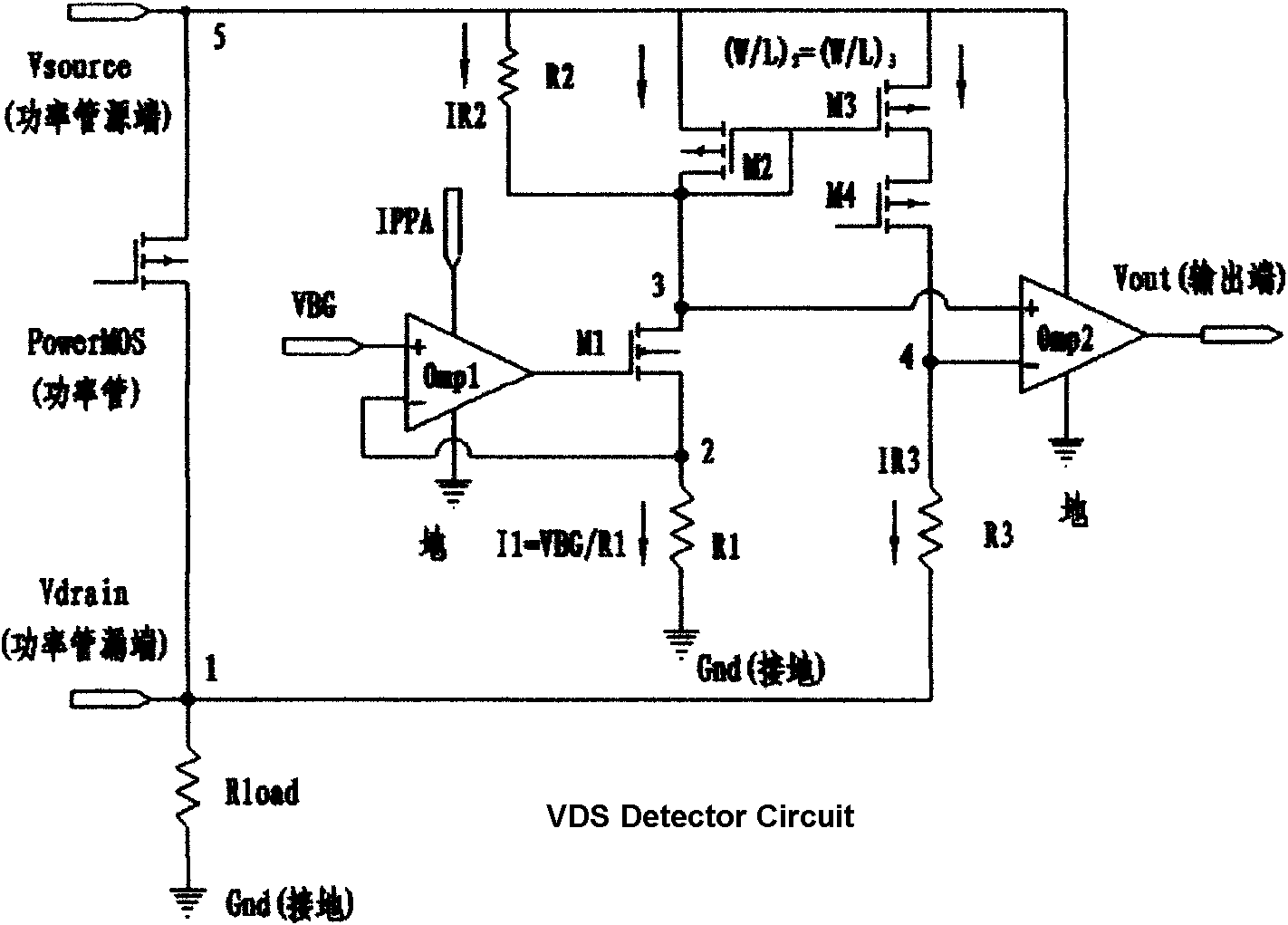
[0020] exist figure 1 Among them, the specific connection relationship of the circuit of the present invention is: the non-inverting input terminal of the operational amplifier omp1 is connected to a reference voltage, here a reference voltage of VBG=1.2V is connected, and the inverting input terminal of the operational amplifier omp1 is connected to the node 2 , the two ends of the resistor R1 are respectively connected to the ground and node 2, the gate of the high-voltage tube M1 is connected to the output terminal of the operational amplifier omp1, the source of the high-voltage tube M1 is connected to the node 2, and the drain of the high-voltage tube M1 The drain of the low-voltage PMOS transistor M2 and one end of the resistor R2 are connected to the node 3, where omp2 is used as an ordinary low-voltage comparator, the non-inverting input terminal of omp2 is connected to the node 3, and the two ends of the resistor R3 are respectively connected to To node 1 and node 4, ...
PUM
 Abstract
Description
Claims
Application Information