Portable electric threader

A threader and portable technology, applied in the field of portable electric threader, can solve the problems of manual injury accidents caused by wire rope scratches, unrecoverable steel wires, and obstruction of the forward movement of steel wires, so as to achieve convenient storage and carrying, fast and smooth threading, clear effect

Active Publication Date: 2015-05-20
BEIJING TIANHENG CONSTR
View PDF5 Cites 3 Cited by
  • Summary
  • Abstract
  • Description
  • Claims
  • Application Information

AI Technical Summary

Problems solved by technology

The shortcoming of this existing known technology and current threading method is: because the steel wire used for threading is relatively hard, if the pipeline bending angle is less than 90 degrees, or the path of the pipelin

Method used


Image

  • Portable electric threader
  • Portable electric threader

Examples


specific Embodiment approach 1

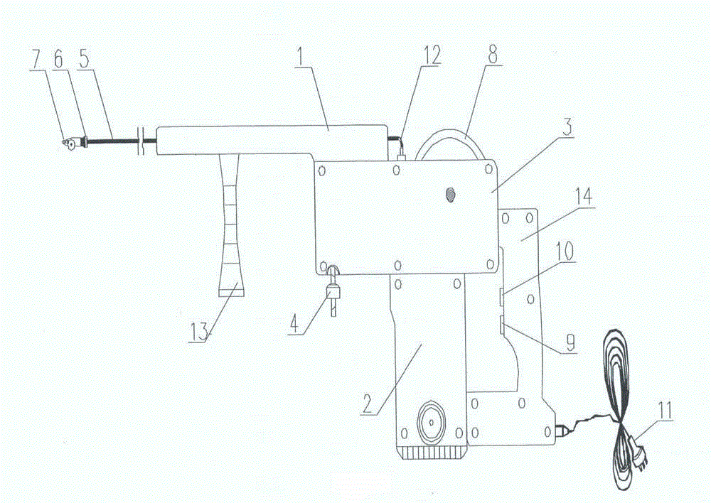
[0038] Below in conjunction with accompanying drawing of description, the present invention is described in detail, just as the accompanying drawing of description figure 1 , figure 2 Shown:

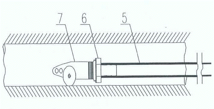
[0039] A portable electric needle threader, which consists of a casing 1, a motor 2, an air pump 3, a filter 4, a hose 5, a joint 6, a warhead 7, a wheel 8, a motor switch 9, an air pump switch 10, a plug 11, an air charging port 12, Handle 13, rear seat 14 constitute;

[0040] The portable electric needle threader, the lower side of the front section of the housing 1 and the upper end of the handle 13, the lower side of the rear end section of the housing 1 and the upper side of the air pump 3, the lower side of the air pump 3 and the motor 2, the rear side of the air pump 3 and the upper end of the rear seat 14, the rear The lower end of the seat 14 is fixedly connected with the motor 2 and the back seat 14 internally with the motor switch 9 and with the air pump switch 10. One side...

specific Embodiment approach 2

[0046] Carry out on the implementation basis of specific embodiment one, just: when applying portable electric needle threader to carry out threading, the perforation that the front end of described bullet 7 is provided with is fixedly connected with the lead wire that is worn and the pulley that bullet 7 middle is provided with needs Threaded pipe slip unions were implemented; also with good results as expected.

specific Embodiment approach 3

[0047] Carry out on the basis of the implementation of the specific embodiment one, just: when using the portable electric threader to remove impurities in the pipeline, the perforation provided at the front end of the bullet 7 is fixedly connected with the brush and the pulley and the pipeline provided in the middle of the bullet 7 Sliding live connections were implemented; also with good results as expected.


PUM


Abstract

The invention discloses a portable electric threader, and relates to the technical field of building engineering industry machine tools. An electric threading key technology is adopted; the lower side of the front segment of a shell and the upper end of a handle, the lower side of the back end segment of the shell and the upper side of an air pump, the lower side of the air pump and a motor, the back side of the air pump and the upper end of a back base, the lower end of the back base and the motor, as well as the inner side of the back base, a motor switch and an air pump switch are fixedly connected; one side of the air pump is in rotary movable connection with a wheel disk through a wheel disk shaft; the front end of the lower side of the air pump is in threaded connection with a filter; the back end of a bullet is in threaded connection with the front end of a joint; the back end of the joint is connected with the front end of a hose; the back end of the hose is spliced with an aerating hole in the air pump, and is fixedly buckled with the aerating hole; the motor, the motor switch and a plug are electrically connected through leads. The portable electric threader is used for threading pipelines or clearing pipeline impurities in building installation engineering. The portable electric threader has the advantages of novel and unique concept, scientific and reasonable design, simple and skillful structure, convenience in use and operation, stable and reliable effect, easiness in manufacturing, low cost, portability, and contribution to popularization.

Description

technical field [0001] The invention relates to a portable electric threader, which relates to the technical field of machinery and tools in the construction engineering industry and its application; in particular, it relates to the technical field of pipeline threading or pipeline impurity removal in construction installation engineering. Background technique [0002] In modern construction and installation projects, it is inevitable to thread the pipeline or remove impurities in the pipeline. Specifically, in construction electrical engineering, industrial installation engineering, intelligent building engineering, municipal engineering, chemical engineering and other industries, such as: metal pipe, plastic pipe and composite pipe laying wires, metal pipe, plastic pipe and composite pipe cleaning. The existing known technology and the current situation are traditional methods. The traditional method has no special appliances and tools, and can only be operated manually. U...

Claims


Application Information

Patent Timeline
IPC IPC(8): H02G1/08
Inventor 张立新杨金锋万成李鹏
Owner BEIJING TIANHENG CONSTR
Why Eureka
Try Eureka