Vacuum cups and vacuum cleaners

A technology of vacuum cleaners and dust cups, applied in suction filters and other directions, can solve the problems of the lip edge of the ash plate that is easy to overflow and overpressure, the decline of the rotation speed of garbage, and the decline of the suction force of the vacuum cleaner, so as to ensure stable operation, large dust collection capacity and good cleaning performance The effect of using demand

Inactive Publication Date: 2017-02-01
安徽省助友塑料笔业有限公司
View PDF5 Cites 0 Cited by
  • Summary
  • Abstract
  • Description
  • Claims
  • Application Information

AI Technical Summary

Problems solved by technology

[0004] When light-weight and bulky garbage enters the first-stage cyclone separation chamber 2', most of the garbage will quickly enter the first-stage dust collection chamber 3', and rotate and accumulate along the inner wall of the dust cup. When the garbage gradually accumulates , the garbage will easily overflow the lip 9' of the dust plate, and return to the primary cyclone separation chamber 2' to continue to rotate. When the rotating garbage gradually increases, the entrance of the auxiliary channel 4' will be easily blocked, causing the vacuum cleaner to The suction decreases, which in turn causes the rotation speed of the garbage to decrease, and the entrance of the auxiliary channel 4' is blocked to further accelerate, and soon there is no suction, and it can no longer be used, resulting in a large reduction in the dust collection capacity of the first-stage dust collection chamber 3'. If you want to expand The dust collection capacity needs to increase the size of the dust cup, which makes the whole machine too large and clumsy

Method used


Image

  • Vacuum cups and vacuum cleaners
  • Vacuum cups and vacuum cleaners
  • Vacuum cups and vacuum cleaners

Examples


Embodiment Construction

[0038] In order to understand the above-mentioned purpose, features and advantages of the present invention more clearly, the present invention will be further described in detail below in conjunction with the accompanying drawings and specific embodiments. It should be noted that, in the case of no conflict, the embodiments of the present application and the features in the embodiments can be combined with each other.

[0039] In the following description, many specific details are set forth in order to fully understand the present invention. However, the present invention can also be implemented in other ways than described here. Therefore, the protection scope of the present invention is not limited by the specific implementation disclosed below. Example limitations.

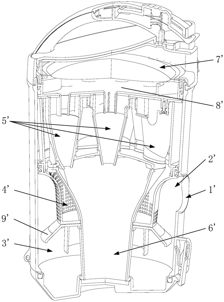
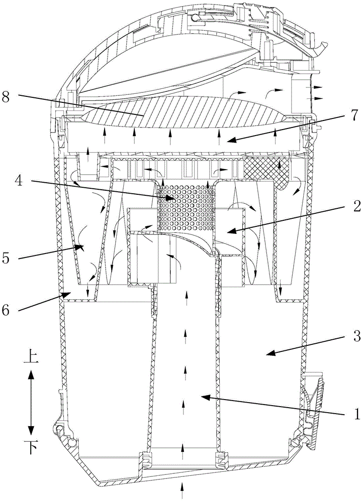
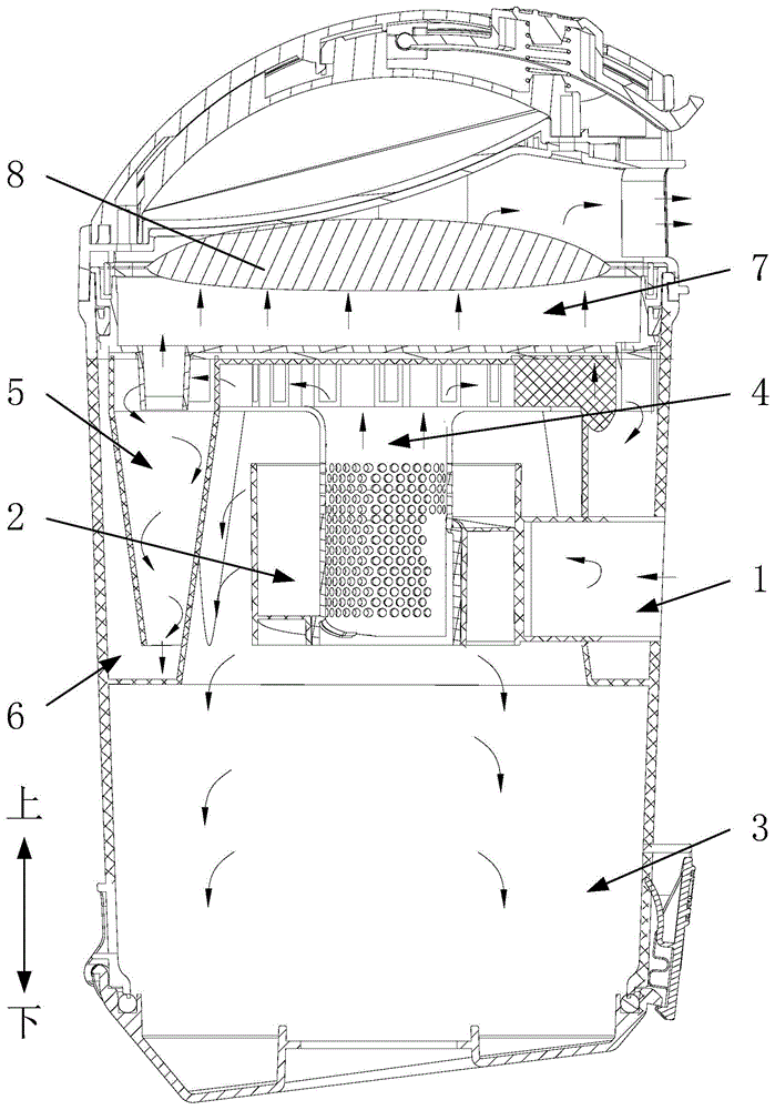
[0040] The dust cup of the vacuum cleaner according to some embodiments of the present invention will be described below with reference to the accompanying drawings.

[0041] The dust cup of the vacuum clean...


PUM


Abstract

The invention provides a dust cup for a dust collector and the dust collector. An air inlet channel, a first-order cyclone separation cavity, a first-order dust collection cavity, an auxiliary channel, a second-order cyclone separation cavity, a second-order dust collection cavity, an air outlet channel and a filter cotton are arranged in the dust cup; the first-order dust collection cavity is arranged below the second-order dust collection cavity, the first-order cyclone separation cavity is arranged in the first-order dust collection cavity, the outlet formed in the upper end of the first-order cyclone separation cavity is communicated with the first-order dust collection cavity, the inlet of the auxiliary channel is arranged in the outlet of the first-order cyclone separation cavity, the second-order cyclone separation cavity is arranged in the second-order dust collection cavity, the outlet of the auxiliary channel is the same with the inlet formed in the upper end of the second-order cyclone separation cavity, the inlet of the air outlet channel is arranged in the inlet of the second-order cyclone separation cavity, the outlet formed in the lower end of the second-order cyclone separation cavity is communicated with the second-order dust collection cavity, and the filter cotton is arranged in the air outlet channel. The dust cup for the dust collector has a novel small and exquisite structure and can well meet the using needs of consumers with large dust collection capacity of the first-order dust collection cavity.

Description

technical field [0001] The invention relates to the field of home appliances, and more specifically, to a dust cup of a vacuum cleaner and a vacuum cleaner. Background technique [0002] Dust cups for vacuum cleaners of existing designs, such as figure 1 As shown, the dust-laden air enters the first-stage cyclone separation chamber 2' from the air intake channel 1', and rotates in the cyclone separation chamber to generate centrifugal force to separate the dust and gas. After separation, the dust (ie: garbage) falls into the first-stage dust collection chamber 3', the dusty air enters the secondary cyclone separation chamber 5' through the auxiliary channel 4' for secondary dust and gas separation, and the garbage falls into the secondary dust collection chamber 6' through the lower opening of the cyclone separation chamber, and the dusty air is then passed through The air outlet channel 7' is discharged, filtered through the filter cotton 8', and finally discharged into th...

Claims


Application Information

Patent Timeline
Patent Type & Authority Patents(China)
IPC IPC(8): A47L9/16
Inventor 刘胜辉牛军营赵岩
Owner 安徽省助友塑料笔业有限公司
Why Eureka
Try Eureka