Gear rack driving type decompressor

A technology of rack and pinion and stamping device is applied in the field of stamping device and rack and pinion driven stamping device, which can solve the problems of high requirement of manufacturing precision of hydraulic components, complicated design of hydraulic system, high operation and maintenance cost, and is convenient for popularization and use. , the effect of high degree of automation and low production cost

Inactive Publication Date: 2015-05-27
XIAN ZHONGZHI HUIZE PHOTOELECTRIC TECH
View PDF0 Cites 6 Cited by
  • Summary
  • Abstract
  • Description
  • Claims
  • Application Information

AI Technical Summary

Problems solved by technology

The stamping device generally uses a hydraulic cylinder to directly drive the stamping head to stamp the workpiece. This method is not labor-saving. In addition, hydraulically driven stam

Method used


Image

  • Gear rack driving type decompressor

Examples


Embodiment Construction

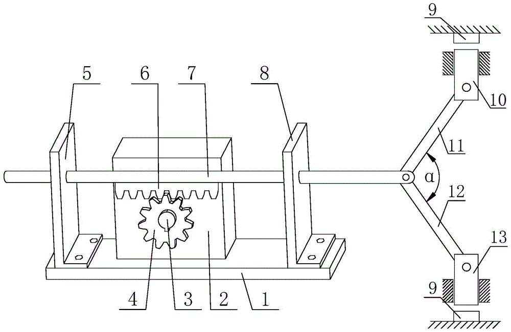
[0020] Such as figure 1 The rack-and-pinion driven stamping device shown includes a rectangular bottom plate 1, a power box 2 fixedly installed on the upper side of the rectangular bottom plate 1 for providing power, and a push rod 7 for transmitting driving force, and also includes a symmetrical Punching head one 10 and punching head two 13 provided for stamping workpiece 9; gear 4 is fixedly installed on the power output shaft 3 of the power box 2, and the gear 4 and the rack 6 mesh with each other to form a rack-and-pinion transmission pair, the rack 6 is fixedly installed on the lower side of the push rod 7, and the push rod 7 is slidably installed on the first support plate 5 and the second support plate 8, and the first support plate 5 and the second support plate 8 All are fixedly installed on the upper side of the rectangular bottom plate 1 by screws, and the front ends of the push rod 7 are respectively connected to one end of the connecting rod one 11 and one end of ...


PUM


Abstract

The invention discloses a gear rack driving type decompressor. The gear rack driving type decompressor comprises a rectangular bottom plate, a power box and a push rod. The gear rack driving type decompressor further comprises a first punching head and a second punching head which are used for punching a work piece; a gear is fixedly installed on a power output shaft of the power box, and the gear is meshed with a rack to form a gear rack transmission pair; the rack is fixedly installed at the downside of the push rod, and the push rod is glidingly installed on a first supporting plate and a second supporting plate; the first supporting plate and the second supporting plate are fixedly installed at upside of the rectangular bottom plate through a screw; the front end of the push rod is respectively and rotationally connected with one end of a first linking rod and a second linking rod, and the other end of the first linking rod is rotationally connected with the first punching head, and the other end of the second linking rod is rotationally connected with the second punching head. The gear rack driving type decompressor has the following characteristics of being reasonable in design, convenient to operate, high in degree of automation, high in production efficiency, time-saving and labor-saving, long in service life, wide in application scale, low in production cost, and convenient to popularize and use.

Description

technical field [0001] The invention belongs to the technical field of mechanical processing, and relates to a punching device, in particular to a rack and pinion driven punching device with two stations. Background technique [0002] Stamping refers to the use of molds to make metal sheets into various sheet-shaped parts, shells, and container workpieces on a punching machine, or to make pipe fittings into various tubular workpieces. In national production, compared with traditional mechanical processing, the stamping process has the advantages of saving materials and energy, high efficiency, low technical requirements for operators, and the ability to produce products that cannot be achieved by mechanical processing through various mold applications. Therefore, It is used more and more widely. The stamping device generally uses a hydraulic cylinder to directly drive the stamping head to stamp the workpiece. This method is not labor-saving. In addition, hydraulically drive...

Claims


Application Information

Patent Timeline
IPC IPC(8): B21D22/02B30B1/24
CPCB21D22/02B30B1/24
Inventor 侯鹏
Owner XIAN ZHONGZHI HUIZE PHOTOELECTRIC TECH
Why Eureka
Try Eureka