Belt conveyor material guide groove

A technology of belt conveyor and guide chute, which is applied in the direction of conveyor objects, transportation and packaging, etc. It can solve the problems of less friction between belt and rubber, affecting the service life of side plates, and damaging conveyor belts, so as to reduce maintenance work The effect of increasing the amount, increasing the service life and prolonging the service life

Inactive Publication Date: 2015-05-27
HENGYANG CONVEYING MACHINERY
View PDF11 Cites 3 Cited by
  • Summary
  • Abstract
  • Description
  • Claims
  • Application Information

AI Technical Summary

Problems solved by technology

The proportion of the material guide groove in the various parts of the belt conveyor is very small, but its role is very important. If the design and installation of the material guide groove are not suitable, it will seriously damage the conveyor belt and pollute the entire system environment
[0003] CN101898676A discloses a material guide trough for a belt conveyor, which includes a bracket, a material guide plate, an upper cover, and a flow guide device. The flow guide device includes a flow guide plate and an adjustment device thereof, and the adjustment device includes an adjustment screw, a nut and a nut bracket. This invention adjusts the centering of the material flow by setting a flow guide device, thereby avoiding the deviation of the belt conveyor, but the flow guide plate in this invention is easy to be damaged due to the wear and tear of the material, and the sealing of the entire material guide groove is not good. Better, some small materials are easy to fly out, polluting the environment of the whole guide trough system
[0004] CN101618799A announces a kind of lift-type guide chute for tape machine, including guide chute body and support, guide chute body is made up of a top plate and two side plates, and the side plate is provided with movable plate, sliding guide rail and for The driving mechanism that drives the movable plate up and down, and the lower end of the movable plate is provided with a sealing rubber. This invention reduces the friction between the tape and the rubber, reduces the power consumption of the tape machine, and makes the sealing between the rubber and the tape better. Good, but the material will also cause friction on the side panels, long-term friction will affect the service life of the side panels, and the seal between the top panel and the side panel brackets is also not guaranteed
[0005] CN103863799A discloses a material guide trough, which includes a short-end connecting plate, a short-end curtain, a short-end bead, a long-end connecting plate, a long-end reinforcing rib, a long-end bead, and a long-end curtain. The short-end curtain of the invention And the long-end curtain utilizes the flexibility of the rubber conveyor belt with three rubbers and two lines, supplemented by a strip curtain structure, and combines with the lifted belt conveyor to achieve the purpose of blocking the material from escaping, but this invention cannot guarantee The tightness between the long-end curtain and the short-end curtain, especially for some small materials, the simple curtain cannot achieve a good sealing effect

Method used


Image

  • Belt conveyor material guide groove
  • Belt conveyor material guide groove
  • Belt conveyor material guide groove

Examples


Embodiment Construction

[0025] The detailed structure of the present invention will be further described below in conjunction with the accompanying drawings and specific embodiments.

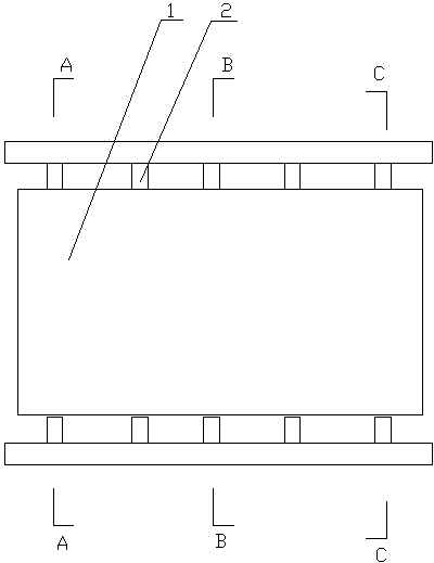
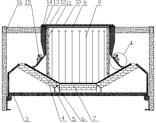
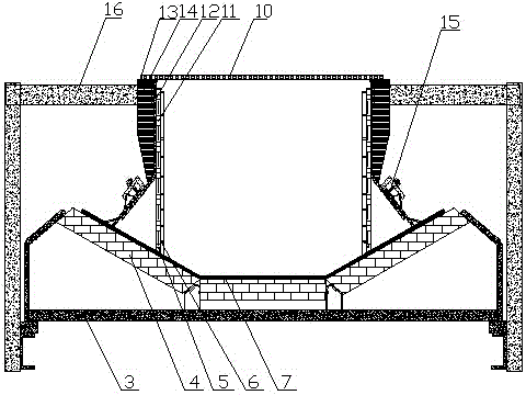
[0026] As shown in the accompanying drawings: a belt conveyor guide trough, including a guide trough body 1, a belt conveyor 2 including an idler 4, an idler bracket 3 and a tape surface 7 on the idler, and the guide trough body 1 The left and right ends are all provided with double front curtains 8, and the right side of the right side double front curtains 8 is also provided with baffle plate 17, and the front and rear sides of feed channel body 1 are all provided with side plates 12, and the upper end of feed channel body 1 is provided with There are cover plates 10, and there are pressure plates 9 under the cover plates 10 at the left and right ends. The pressure plates 9 can enhance the stability of the cover plates 10, thereby enhancing the sealing effect; the surface of the upper side plate 12 in contact with the...


PUM


Abstract

The invention provides a belt conveyor material guide groove, which comprises a material guide groove body, wherein the material guide groove body comprises a support roller, a support roller support frame and a rubber belt surface arranged on the support roller, the left end and the right end of the material guide groove body are respectively provided with double front curtains, the right sides of the double front curtains arranged at the right side are also provided with a baffle plate, side plates are respectively arranged at the front side and the back side inside the material guide groove body, a cover plate is arranged at the upper end of the material guide groove body, a press plate is also arranged under the cover plates arranged at the left and right ends, a lattice making lining plate is arranged on the surface, in contact with the materials, of the upper section side plate, and an overflowing-proof skirt edge is arranged on the lower section side plate; a first sealing plate is arranged between the cover plate and the side plates, and a second sealing plate is arranged at a surface contact part of the lattice making lining plate and the rubber belt surface; the support roller support frame and the side plates are connected through adjustable angle steel, and reinforcing ribs are also arranged between the side plate and the adjustable angle steel. The belt conveyor material guide groove provided by the invention has the advantages that the structure is simple, the cost is low, the sealing is tight, the wear resistance of the side plates is high, and the like.

Description

technical field [0001] The invention relates to a material conveying device, in particular to a material guide groove of a belt conveyor. Background technique [0002] Belt conveyor is the main equipment for modern bulk material transportation. It is widely used in metallurgy, mining, coal, port, chemical industry, water conservancy, electric power and many other industries. As an important part of belt conveyor, the guide chute is reliable. The necessary conditions for the normal operation of belt conveyors. With the wide application of large bandwidth, large capacity, high efficiency and energy saving, economical and environmentally friendly belt conveyors, the requirements for the use of belt conveyor guide grooves are also getting higher and higher. The proportion of feed chute in the parts of belt conveyor is very small, but its function is very important. If the design and installation of feed trough are not suitable, it will seriously damage the conveyor belt and poll...

Claims


Application Information

Patent Timeline
Patent Type & Authority Applications(China)
IPC IPC(8): B65G47/18
Inventor 廖纯徳刘艳向军贺小飞
Owner HENGYANG CONVEYING MACHINERY
Why Eureka
Try Eureka