Large-span self-anchored suspension bridge hoisting construction method and temporary tower-girder anchoring device

A construction method and temporary anchor technology, which are applied in the directions of bridges, bridge construction, erection/assembly of bridges, etc., can solve the problems of low thrust resistance of side span buttresses, large construction risks, limited horizontal force, etc., and achieve a simple and reliable construction process. , The effect of reducing risk factors and fast construction progress

Inactive Publication Date: 2015-05-27
CHANGAN UNIV
View PDF6 Cites 11 Cited by
  • Summary
  • Abstract
  • Description
  • Claims
  • Application Information

AI Technical Summary

Problems solved by technology

[0007] The advantage of the temporary ground anchor method is that the force transmission path is clear, but due to the need to excavate the foundation and set up a large-volume temporary ground anchor, there are certain requirements for the bearing capacity of the ground, and the economy is poor; Construction risks are high
The pier-be

Method used


Image

  • Large-span self-anchored suspension bridge hoisting construction method and temporary tower-girder anchoring device
  • Large-span self-anchored suspension bridge hoisting construction method and temporary tower-girder anchoring device
  • Large-span self-anchored suspension bridge hoisting construction method and temporary tower-girder anchoring device

Examples


Embodiment 1

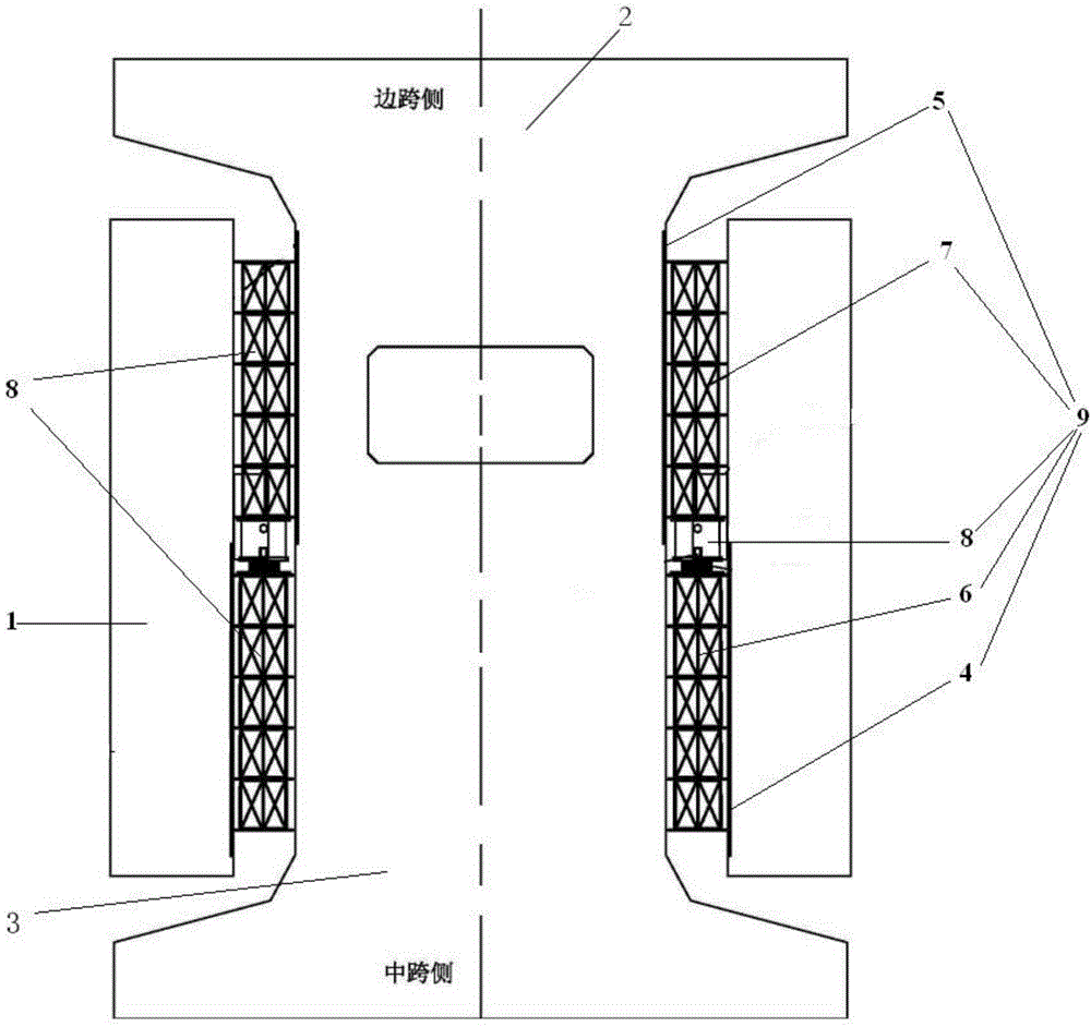
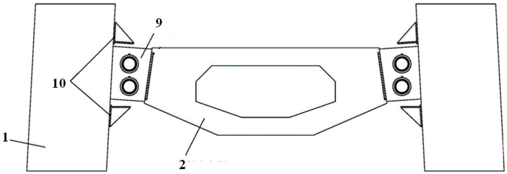
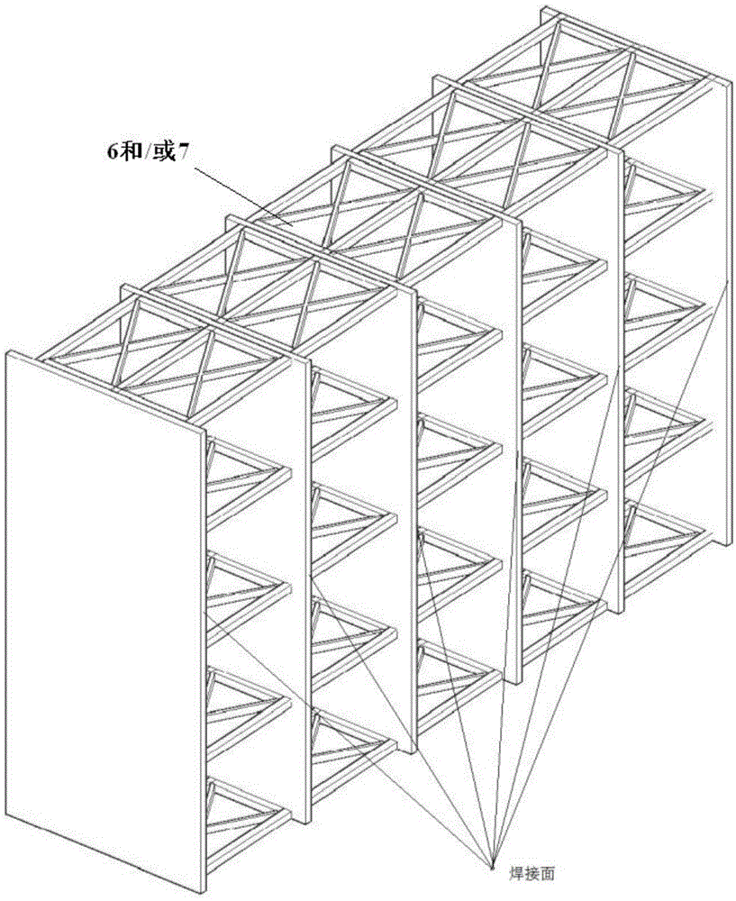
[0051] This embodiment provides a kind of tower beam temporary anchoring device, including the first pre-embedded steel plate 4 pre-set on the side wall of the bridge tower 1 near the side of the middle span, and pre-set on the side wall of the main girder 2 of the side span near the side of the side span The second embedded steel plate 5, the first embedded steel plate 4 is fixedly installed with the first grid frame 6, the second embedded steel plate 5 is fixedly installed with the second grid frame 7, the first grid frame 6 and the second The axial centerlines of the two grid frames 7 are on the same axis parallel to the side span main beam 2 vehicle traveling direction, so that an end face of the first grid frame 6 and an end face of the second grid frame 7 are arranged oppositely, Form the action surface of the force transmission brace 8;

[0052] The two opposite end surfaces of the first grid frame 6 and the second grid frame 7 are supported by force transmission braces...

Embodiment 2

[0060] This embodiment provides a hoisting construction method for a large-span self-anchored suspension bridge using the tower beam temporary anchoring device described in Embodiment 1. During the construction process, the side span main beam 2 is supported by the tower beam temporary anchoring device. The horizontal force is transmitted to the bridge tower 1. This construction method is suitable for the double-tower three-span self-anchored suspension bridge structure in which the side-span main girder 2 is a concrete main girder and the mid-span main girder 3 is a steel main girder. It specifically includes the following steps:

[0061] Step 1, carry out foundation treatment to the foundation of the bridge tower 1 of bridge, construction pier foundation 11, bridge tower 1 and side-span bridge pier 12, such as Image 6 shown;

[0062] Step 2, set up side-span temporary pier or support 13, cast-in-situ concrete main girder on side-span temporary pier or support 13, stretch pr...


PUM

PropertyMeasurementUnit
Lengthaaaaaaaaaa
The inside diameter ofaaaaaaaaaa
Outer diameteraaaaaaaaaa

Abstract

The invention provides a temporary tower-girder anchoring device. One end surface of a first grid is arranged opposite to one end surface of a second grid, so that acting surfaces of force transfer supports are formed; the two oppositely arranged end surfaces of the first grid and the second grid are supported by the force transfer supports to transfer force, so that horizontal force applied on a side span girder can be transferred to a bridge tower in the process of construction; a jack is mounted in a telescopic sleeve composed of an inner barrel and an outer barrel, one end of the jack is fixedly connected with a steel frame arranged on the end of the outer barrel far from the inner barrel, and an oil tube of the jack enters the outer barrel through an oil tube port arranged on the sidewall of the outer barrel. A large-span self-anchored suspension bridge hoisting construction method adopting the temporary tower-girder anchoring device transfers the horizontal force applied on the side span girder to the bridge tower by means of the temporary tower-girder anchoring device in the process of construction.

Description

technical field [0001] The invention belongs to the construction field of suspension bridges, and relates to a self-anchored suspension bridge, in particular to a hoisting construction method for a double-tower, three-span, large-span self-anchored suspension bridge, and a temporary anchoring device for bridge towers and side-span main girders. Background technique [0002] Compared with the ground-anchored suspension bridge, the self-anchored suspension bridge does not need huge anchors. The main cable is anchored at the end of the main girder of the side span, and the main girder bears the horizontal and vertical components of the main cable. It is beautiful, reasonable in force, economical and applicable, and solves the problem that the geological conditions do not allow the construction of anchorages and the construction of suspension bridges. [0003] Since the main cable of the self-anchored suspension bridge is anchored on the main girder, the main cable generates a h...

Claims


Application Information

Patent Timeline
IPC IPC(8): E01D21/00
CPCE01D21/00
Inventor 王晓明李红玉段瑞芳胡明雷晓鸣段玮冯加利蔡京洋
Owner CHANGAN UNIV
Why Eureka
Try Eureka