Piezoelectric and solar complementary smart luminous floor
What is Al technical title?
Al technical title is built by PatSnap Al team. It summarizes the technical point description of the patent document.
A luminescent floor and solar energy technology, which is applied in the direction of current collectors, electric vehicles, electrical components, etc., can solve the problems of inconvenient turning on lights, difficulties in speed and safety, and single power supply mode, and achieve accurate signal transmission, reasonable charging mechanism, and guaranteed The effect of normal power supply
Active Publication Date: 2016-11-23
STATE GRID CORP OF CHINA +1
View PDF5 Cites 0 Cited by
Summary
Abstract
Description
Claims
Application Information
AI Technical Summary
This helps you quickly interpret patents by identifying the three key elements:
Problems solved by technology
Method used
Benefits of technology
Problems solved by technology
[0005] The above-mentioned technical solution only has a single power supply mode, which cannot make full use of the conditions to generate electric energy. When people walk less on the floor, only the power generated by the cutting magnetic field may be insufficient to complete the power supply task.
Furthermore, when people walk at night, it may be inconvenient to turn on the lights, or they need to see the road ahead in advance
Ordinary luminous floors cannot intelligently identify the direction of people walking, which brings certain difficulties to the speed and safety of people walking
Method used
Image
Click on the blue label to locate the original text in one second.
Reading with bidirectional positioning of images and text.
Examples
Embodiment Construction
[0030] Below in conjunction with accompanying drawing, the present invention is described in further detail:
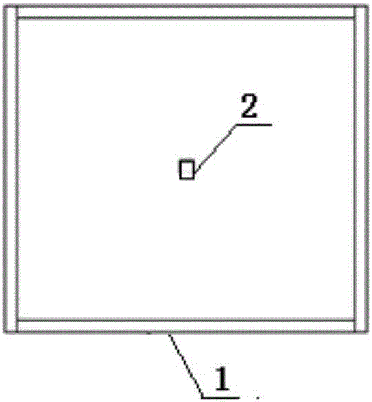
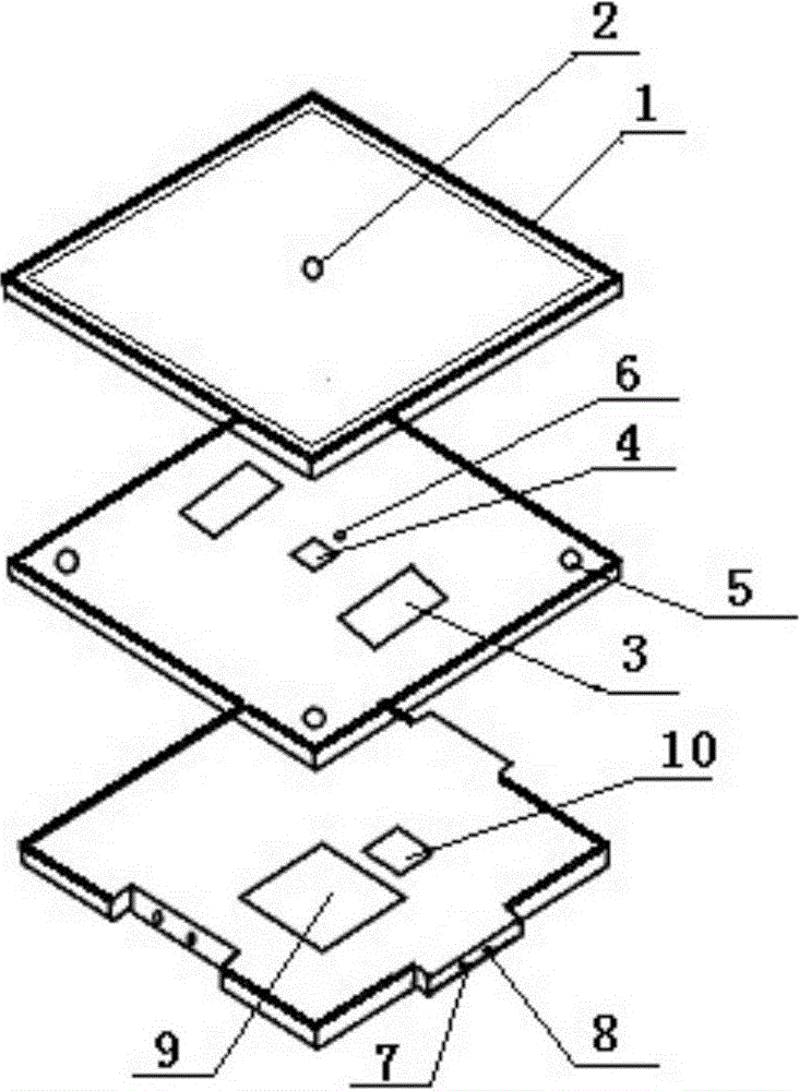
[0031]The intelligent light-emitting floor that complements piezoelectricity and solar energy is composed of three layers. The first layer includes a transparent plate, a soft material 1, and a protruding cylinder 2 set at the center of the transparent plate. The soft material 1 is surrounded by the transparent plate; The light transmittance of the transparent plate can make the solar power generation panel 3 receive light and generate electricity. There is a soft material 1 with a width of 1 cm and a thickness of 0.5 cm around the transparent plate, so that the transparent plate supports a space of 0.5 cm in height. When it is put on, the transparent plate deforms, and the protruding cylinder 2 with a height of 0.2 cm squeezes the piezoelectric generator sheet 4, and the piezoelectric generator sheet 4 deforms to generate electricity. The second layer mainly includes...
PUM
Abstract
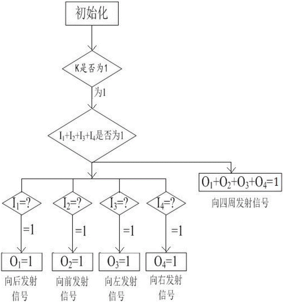
The invention discloses a piezoelectric and solar complementary intelligent light emitting floorboard. Specifically, the intelligent light emitting floorboard can pre-illuminate and be automatically charged and consists of three layers, namely a first layer, a second layer and a third layer, wherein the first layer comprises a transparent plate, a soft material surrounding around the transparent plate and a protruding column body arranged at the center of the transparent plate; the second layer mainly comprises a PVC (Polyvinyl Chloride) plate A, a piezoelectric power generation sheet, solar power generation panels, a photosensitive resistor and LED (Light Emitting Diode) lamps, wherein the piezoelectric power generation sheet, the solar power generation panels, the photosensitive resistor and the LED lamps are embedded in the PVC plate A; the third layer comprises a PVC plate B, a circuit board, a super capacitor, infrared transmitting tubes and infrared receiving tubes, wherein the edges of the PVC plate B are of concave-convex groove-wedge structures, the circuit board, the super capacitor, the infrared transmitting tubes and the infrared receiving tubes are built in the PVC plate B, and a singlechip microcomputer and an LED lighting module are arranged on the circuit board; the photosensitive resistor, a piezoelectric module, an infrared receiving module, an infrared transmitting module and the LED lighting module are all connected with singlechip microcomputer. According to the intelligent light emitting floorboard, intelligent human walking direction judgment and in-advance lighting can be achieved; a charging mechanism is reasonable, and the normal power supply of devices is guaranteed; disassembly is facilitated.
Description
technical field [0001] The invention relates to a luminous floor, in particular to an intelligent floor capable of pre-luminous and automatic charging. Background technique [0002] Flooring is the surface layer of the ground or floor of a building, made of wood or other materials. There are many classifications of floors, classified by structure: solid wood floor, laminated composite wood floor, bamboo wood floor and the most popular multi-layer solid wood composite floor, etc.; classified by use: household, commercial, anti-static floor, sports hall Special floor for venues, special floor for track and field, etc. In addition, there are some floors with specific functions formed by adding special structures to the basic floor. The luminous floor is a special floor, which is mostly used in stairs, living rooms, children's activity places, etc. [0003] The luminous floor is generally a multi-layer composite floor with a luminous layer in the middle. The light-emitting m...
Claims
Application Information
Patent Timeline
Application Date:The date an application was filed.
Publication Date:The date a patent or application was officially published.
First Publication Date:The earliest publication date of a patent with the same application number.
Issue Date:Publication date of the patent grant document.
PCT Entry Date:The Entry date of PCT National Phase.
Estimated Expiry Date:The statutory expiry date of a patent right according to the Patent Law, and it is the longest term of protection that the patent right can achieve without the termination of the patent right due to other reasons(Term extension factor has been taken into account ).
Invalid Date:Actual expiry date is based on effective date or publication date of legal transaction data of invalid patent.